3-16 Quick guide for installation and use - Strider Transmitter Link
Strider Link Series
SRFStrider-161004A-REV.A
Sinteck Sistemas Eletrônicos Ltda.
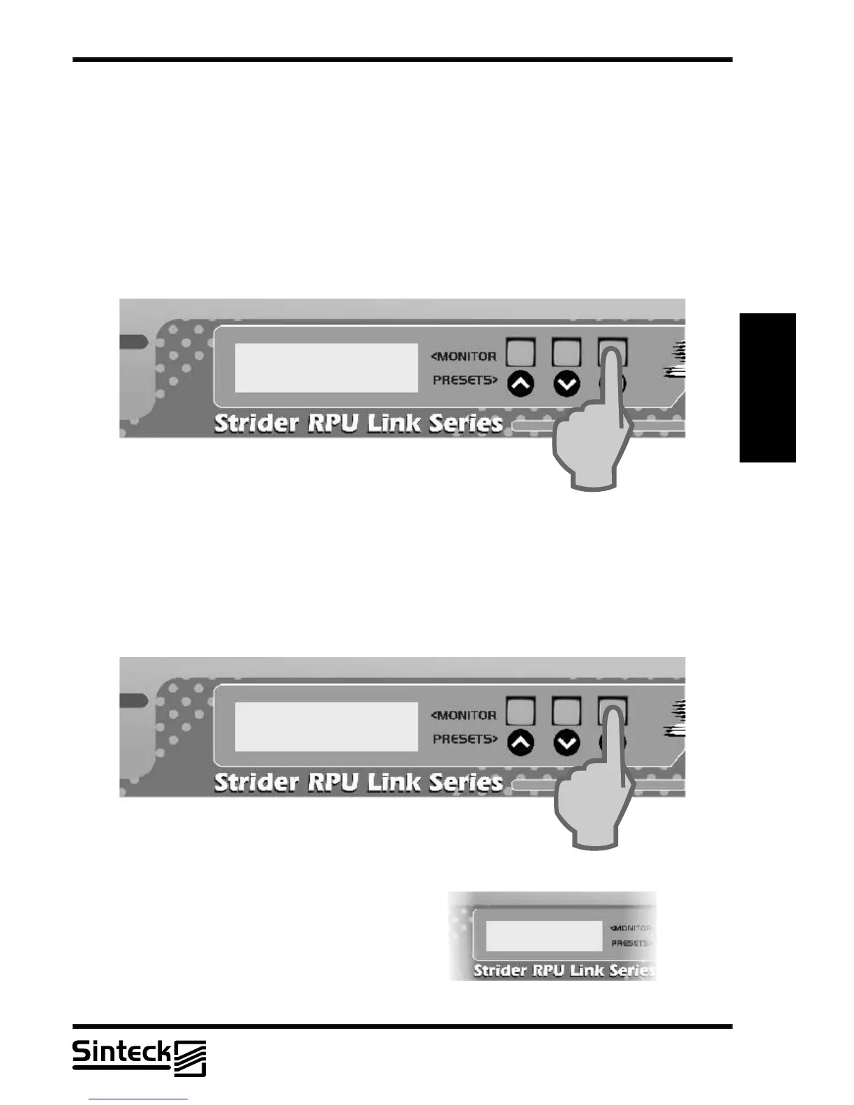
POWERAMPLIFIER STATUS MENU
This view shows to the user the status of the P.Aof the Strider Transmitter Link.
1) VPA- Voltage presents in the RF module
2) IPA- Current absorbed for the RF module
This menu is only to show the Voltage and Current of the P.A.Any parameter is not adjusted
here. The Voltage and Current will be modified if is setted other value in the menu
“ADJUSTING THE RF POWER”.
3
CONFIG HOLD MENU
This menu disables to set all adjustables menus. Pressing the button “UP” the equipment
now cannot change channels, contrast, RF level, disable or enable cards.
Also, this view permisses to show the Bias voltage presents on the RF power module. This
value is changed when the RF power output is setted.
VPA: 7,48V
IPA: 2,40A
To return to the original position in the “CONFIG
HOLD” the button “DOWN” must to be pressed.
REMARK: If the Strider Transmitter Link
doesn’t respond the buttons “UP” and “DOWN”
do verify if the “CONFIG HOLD” is enabled.
This function is most important for who needs a
system that nobody has access to change the
parameters (channels, RF power, etc.)
03/P/35