Snifter mA+ EX RF User Manual 7
3 WIRING
The Snifter mA+ EX RF comes with two meter power and signal cable. There are 12
wires in the same cable, two wires for VDC power source, two for alarm signals,
and one for automatic setup signal. Remaining wires are left for digital
communication with Sintrol Dustlog software.
Connect the VDC power supply to pink (+) and GND to gray (-) wires. Blue and red
wires are for alarm signals and they give the same voltage levels as power input
voltage, when the alarm latches to high state.
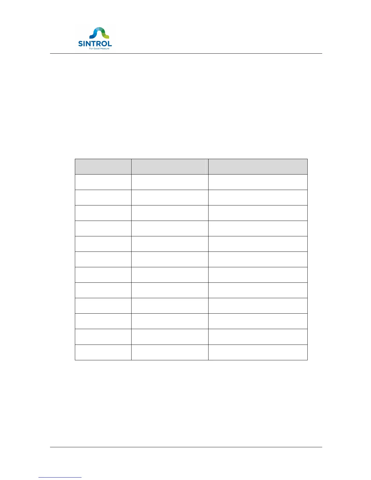
PCB pin Wire colour Signal name
1 BLUE Alarm signal 1
2 RED Alarm signal 2
3 BLACK 4 – 20 mA +
4 YELLOW 4 – 20 mA -
5 GRAY V- (GND)
6 PINK V+ (VDC)
7 GREEN Automatic setup
8 BROWN RS 485 D+
9 WHITE RS 485 D-
10 BLUE/RED USB DM
11 GRAY/PINK USB DP
12 VIOLET USB VBUS
Table 1 Wiring and signals
Snifter mA+ EX RF can be powered by using only USB connection for the purpose of
accessing and adjusting parameters with appropriate Sintrol PC software. More
information about parameter adjustment can be found in section 7 of this manual.