9
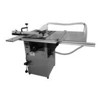
6. Assembly handw
heel saw blade tilting
• Place the handwheel for saw blade tilting on
the shaft.
• The flattened side at the shaft (1) must be
exactly in line with the Allen screw (2) on the
handwheel.
• Push the handwheel completely onto the
shaft and tighten the Allen screw (2) with
Allen key (3).
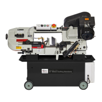
7. Check saw bl
ade alignment to main table
• The T-slots on the main table must be aligned
parallel to the saw blade.
• If the deviation is greater, the following
adjustments can still be made.
1. Loosen the mounting screws (1) and the
saw unit parallel by the play of the screws.
2. Tighten the screws again after the
adjustment.
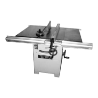
8. Assembly sliding table
SIP Code 01481 (Optional)
8.1. Sliding table
brackets
• Unscrew the two screws (2) at the two sliding
table brackets (1).
• Ins
ert 2 Allen screws (2) each in the
corresponding boreholes (3) on both sides of
the worktable (4).
• Position the two sliding table brackets (1)
laterally at the underside of the worktable
and tighten the Allen screws (2) well at the
top using an Allen key.
5. ASSEMBLY Cont...