8
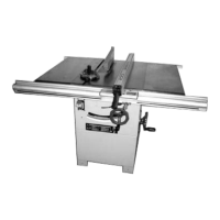
2. Assembly m
achine feet
• Screw the 4 machine feet into the threaded
holes at the corners of the socket (1).
NOTE: Make sure that the machine is aligned
horizontally (spirit level).
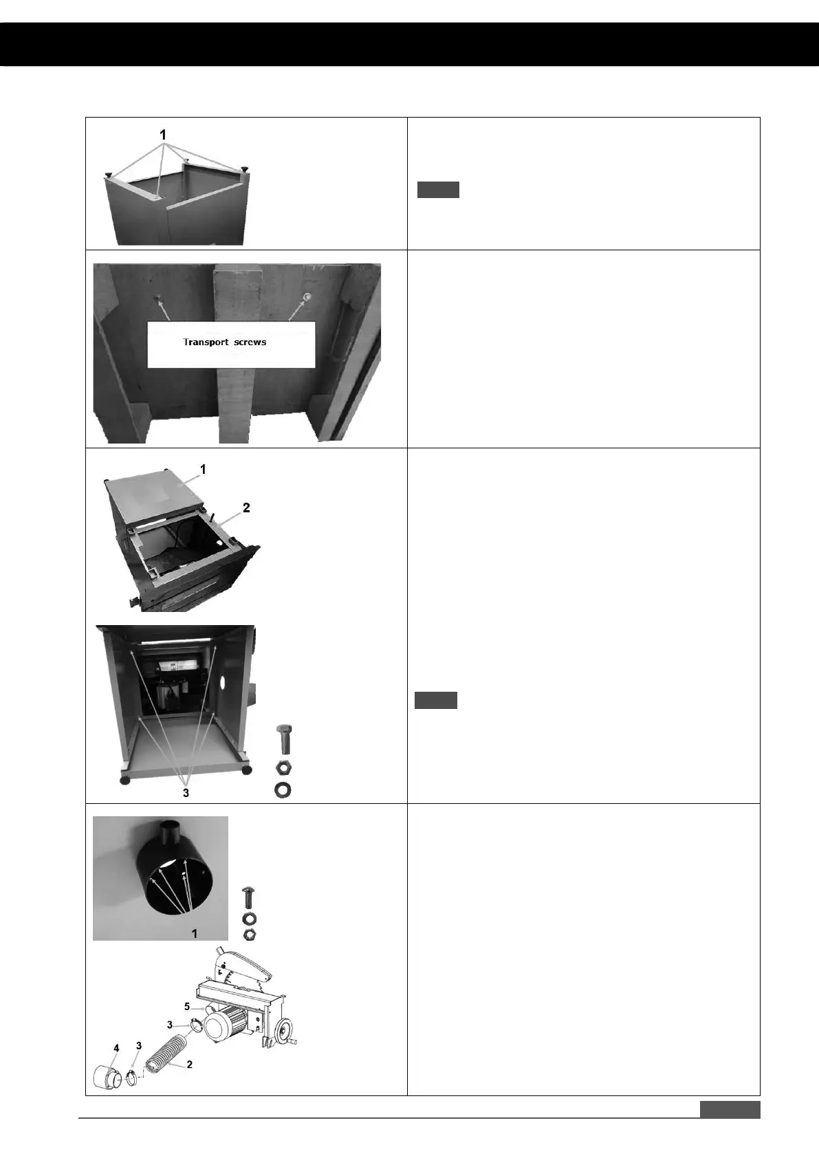
3. Disassembl
y of wooden transport base
• Tilt the machine onto a carton base.
• Remove the transport screws with a wrench.
• If the nuts rotate in the machine, it is possible
to grip laterally into the machine to secure
the nuts against rotation.
• Remove the components, included in the
delivery
content, from the inside of the
machine.
4. Assembly s
ocket on machine
• Because the machine is heavy, it is
recommended to tilt the socket (1) and the
machine (2) and to connect them while lying
on a horizontal surface.
• Socket and machine are connected at the
boreholes in the corners (3) with screws
M6x20, washers and nuts.
NOTE: The machine is heavy! 2 persons are
required to raise the machine.
5. Assembly suction hose Ø 70 mm
5.1. Suction socket
• Mount the suction socket laterally on the
machine with 4 Phillips screws M5x15,
washers and nuts (1).
5.2. Suction hose Ø 70 mm
• Attach one end of the suction hose Ø 70 mm
(2) with a hose clamp (3) at the suction socket
(4) on the inside of the machine.
• Attach the other end of the suction hose Ø 70
mm (2) to the outlet (5) of the lower saw blade
guide with a hose clamp (3).
5. ASSEMBLY Cont...
 Loading...