6
SAFETY INSTRUCTIONS….cont
signed.
DO NOT OPERATE THE MIG WELDER IN EXPLOSIVE ATMOSPHERES: Do not use the mig
welder in the presence of flammable liquids, gases, dust or other combustible
sources. Mig welding will create sparks which can ignite the dust or fumes.
DO NOT EXPOSE THE MIG WELDER TO RAIN OR USE IT IN WET CONDITIONS: Water enter-
ing the mig welder will greatly increase the risk of electric shock.
HAVE YOUR MIG WELDER REPAIRED BY A QUALIFIED PERSON: The mig welder is in ac-
cordance with the relevant safety requirements. Repairs should only be carried out by
qualified persons using original spare parts, otherwise this may result in considerable
danger to the user.
Stop operation immediately if you notice anything abnormal.
Always disconnect the plug from the mains supply before cleaning or servicing
etc.
Be alert at all times, especially during repetitive, monotonous operations; Don't
be lulled into a false sense of security.
Use of improper accessories may cause damage to the mig welder and sur-
rounding area as well as increasing the risk of injury.
Do not modify the mig welder to do tasks other than those intended.
To avoid injury, the work-piece should never be held with the bare hands.
Appropriate personal protective equipment MUST be worn and MUST be de-
signed to protect against all hazards created. Severe permanent injury can re-
sult from using inappropriate or insufficient protective equipment - Eyes in par-
ticular are at risk.
The work must be clamped firmly whilst welding, If its loose it could result in per-
sonal injury, damage to the machine or to the item that is being welded.
DO NOT attempt any repairs unless you are a competent electrician or engi-
neer.
Ensure that the machine is connected to the correct supply voltage and pro-
tected by a fuse or circuit breaker of the recommend rating.
31
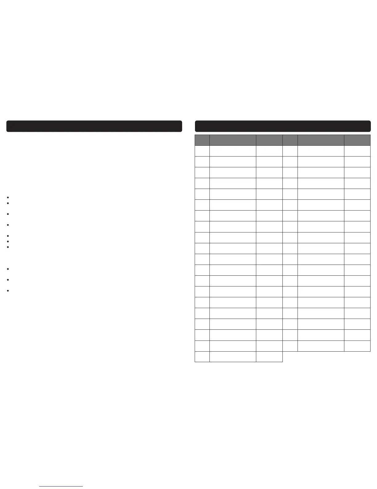
PARTS LIST WELDMATE T136 MIG
Ref. No. Description Sip Part No. Ref. No. Description Sip Part No.
1. Left side panel WE02-00035 21. Fan support WE02-00022
2. Hinge WE02-00029 22. Fan motor WE02-00023
3. Lock WE02-00002 23. Fan Blade WE02-00024
4. Wire feed motor WE02-00036 24. Right side panel WE02-00040
5. Front panel WE02-00003 25. Handle WE02-00015
6. Rocker switch WE02-00005 26. Mains lead WE02-00027
7. On/Off switch WE02-00004 27. Rear panel WE02-00041
8. Thermal overload light WE02-00006 28A. Gas hose connector WE02-00042
9. Potentiometer knob WE02-00007 28B. Gas valve connector WE02-00043
10. Welding torch 02741 29. Rectifier WE02-00044
11. Earth return lead WE02-00010 30. Rectifier support WE02-00045
12. Cable grommet WE02-00009 31. Breaker WE02-00020
13. Cable clamp WE02-00011 32. Auxiliary transformer WE02-00031
14. PCB holder WE02-00013 33. Centre panel WE02-00046
15. PCB WE02-00037 34. Positive terminal WE02-00047
16. Foot WE02-00019 35. Wire spool holder WE02-00030
17. Lower panel WE02-00038 36. Negative terminal WE02-00048
18. Mains filter WE02-00016 37. Fuse WE02-00032
19. Thermostat WE01-00039 N/A. Wire feed roller 0.6-0.8 WE02-00049
20. Transformer c/w choke WE02-00040
 Loading...