Do you have a question about the Sisu Diesel 320 and is the answer not in the manual?
Explains the coding system for identifying different Sisu Diesel engine types based on application.
Provides guidance on the correct procedure for safely lifting the engine using a lifting device.
Illustrates the positions where the engine serial number can be found on different engine models.
Details the dimensions and specifications for the engine's cylinder block.
Provides dimensional data for cylinder liners, including protrusion and diameters.
Lists specifications for the cylinder head, including dimensions and valve guide details.
Contains technical data for valve train components like valves, rockers, and tappets.
Specifies dimensions and clearances for the camshaft and its bearings.
Details crankshaft journal diameters, lengths, and clearances.
Lists specifications for the flywheel, including ring gear and unbalance limits.
Provides technical data for the balancing unit specific to 420-series engines.
Contains specifications for timing gears, including tooth backlash and shaft dimensions.
Details dimensions for connecting rods, including pin bushings and big end bearings.
Specifies dimensions for pistons, piston rings, and piston pins.
Provides technical data for the lubrication system, including oil pressure and pump specifications.
Lists dimensions and clearances for the oil pump used in 320 and 420 engines.
Provides specifications for the oil pump used in 620 and 634 engines.
Details specifications for the coolant pump used in 320 and 420 engines.
Provides specifications for coolant pumps with separate ball bearings for 320/420 engines.
Lists part numbers and opening temperatures for various thermostat types.
Contains specifications for turbocharger shaft float and radial clearance.
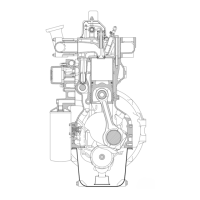
Provides a general overview of the Sisu Diesel 20/34 series engines.
Describes the construction and features of the engine's cylinder block.
Explains the construction and mounting of the flywheel housing.
Details the construction of the crankshaft, including bearings and connecting rods.
Describes the cylinder head construction, bolts, and valve guides.
Explains the operation and components of the valve mechanism.
Describes the construction of the timing gear train and its components.
Explains the engine's pressure lubricating system and its components.
Describes the engine's cooling system, including the pump and thermostat.
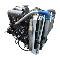
Details the construction of the inlet and exhaust systems, including the turbocharger.
Explains the Sisu Diesel EEM system, a microprocessor-based engine control system.
Details the procedure for measuring cylinder liner wear using a dial gauge.
Describes how to remove cylinder liners using a specialized puller tool.
Outlines steps for cleaning and checking the cylinder block for damage or wear.
Explains the process of removing and installing camshaft bushings.
Details the procedure for fitting the flywheel housing, including sealant and bolts.
Describes how to remove and replace the crankshaft rear oil seal.
Provides steps for removing the cylinder head and associated components.
Details the procedure for removing valves and valve train components.
Explains how to clean and check the cylinder head for flatness and cracks.
Describes the process of reconditioning valve train components like tappets and rocker arms.
Details the procedure for removing the crankshaft from the engine.
Explains how to clean and measure crankshaft journals for wear.
Describes the process of removing and fitting crankshaft gears.
Details the procedure for removing pistons and connecting rods from the engine.
Explains how to change connecting rod big end bearings.
Describes how to check connecting rods for damage or wear.
Details steps for removing and dismantling the counterbalance unit.
Explains how to check and recondition counterbalance unit components.
Describes the procedure for fitting the counterbalance unit.
Details how to change the starter ring gear on the flywheel.
Explains the procedure for fitting the flywheel to the crankshaft.
Provides steps for removing the timing gear casing and related components.
Explains how to recondition the idler gear and its bushing.
Details how to recondition the oil relief valve for lubricating oil pressure.
Explains the procedure for removing and dismantling the lubricating oil pump.
Describes the thermostat's function and how to check its operation.
Details the process for reconditioning the coolant pump for 320 and 420 engines.
Explains the importance of the air cleaner and how to check its condition.
Highlights the significance of leak-free inlet and exhaust pipes for turbocharger performance.
Provides a method for diagnosing potential faults in the turbocharger.
Covers repair and service for the in-line fuel injection pump.
Details the type and construction of the fuel feed pump.
Lists the type and sealing ring part number for injectors.
Specifies tightening torques for various fuel system components.
Technical data for the CAV DPA type distributor pump.
Lists types, injection order, and rotation direction for CAV pumps.
Describes the construction and pressure specifications of the CAV fuel feed pump.
Specifies control pressure and sealing ring for CAV injectors.
Lists tightening torques for CAV pump components.
Equipment and feeding table data for 320 engine applications.
Equipment and feeding table data for 420 engine applications.
Equipment and feeding table data for 420 engine applications.
Equipment and feeding table data for 420 engine applications.
Equipment and feeding table data for 420 engine applications.
Equipment and feeding table data for 420 engine applications.
Equipment and feeding table data for 420 engine applications.
Equipment and feeding table data for 620 engine applications.
Equipment and feeding table data for 620 engine applications.
Equipment and feeding table data for 620 engine applications.
Equipment and feeding table data for 634 engine applications.
Equipment and feeding table data for 634 engine applications.
Details specifications for various Magneti Marelli and Bosch alternators.
Provides further specifications for Magneti Marelli and Bosch alternators.
Lists specifications for Iskra and Bosch alternators.
Details specifications for Iskra alternators.
Provides specifications for Iskra alternators.
Details specifications for Iskra alternators.
Explains the assembly and electrical connection of the electric stop device.
Describes methods to check the solenoid plunger operation for Synchro start.
Explains how to test the external circuit of the solenoid.
Describes how to check solenoid plunger operation for Elettrostart.
Details the installation procedure for the magnetic pick-up sensor.
Provides specifications and resistance values for the temperature sensor.
Details the inspection and disassembly of the Bendix compressor.
Step-by-step instructions for disassembling the Bendix compressor.
Provides inspection and reassembly instructions for the Knorr compressor.
Details the service and adjustment procedures for the industrial clutch.
Service notes for the industrial clutch, emphasizing safety.
Describes the adjustment procedure for the industrial clutch engagement load.
| Brand | Sisu Diesel |
|---|---|
| Model | 320 |
| Category | Engine |
| Language | English |