INSTALLATION
Main gas connection
The connection is made using gas pipes with Rp 1/2 ISO 7 (or Rp 3/4) threading. Torque:
25 Nm. If, alternatively, flanges (available on request) are used, first screw the pipes onto
the flanges and then the flanges to the control. Recommended torque for the flange
fixing screws: 3 Nm.
Connection to the pilot burner
Pipes with a 4 mm, 6 mm or 1/4 diameter can be used. Use a nut and olive of appropriate
dimensions. Tighten to 7 Nm torque.
Electrical connections
All the electrical connections should be made in compliance with the provisions of the electrical
standards in force. Check that the voltage and frequency of the coils, indicated on the control,
are correct. Check that all the connections, in particular the earth, are carried out to industry
standards.
The 24Vac versions must be powered by an isolating transformer (with very low safety voltage).
Carry out the connections in accordance with the rules for the appliance.
To access the supply and earth terminals, unscrew the screw and remove the cover. To
access the electric ignition enabling terminals “W” (where applicable), unscrew the screw “M”
and remove the enabling device. The limit thermostat “LS” should be inserted into the ther-
moelectric circuit.
CAUTION: after making the connections, check gas tightness and electrical insulation.
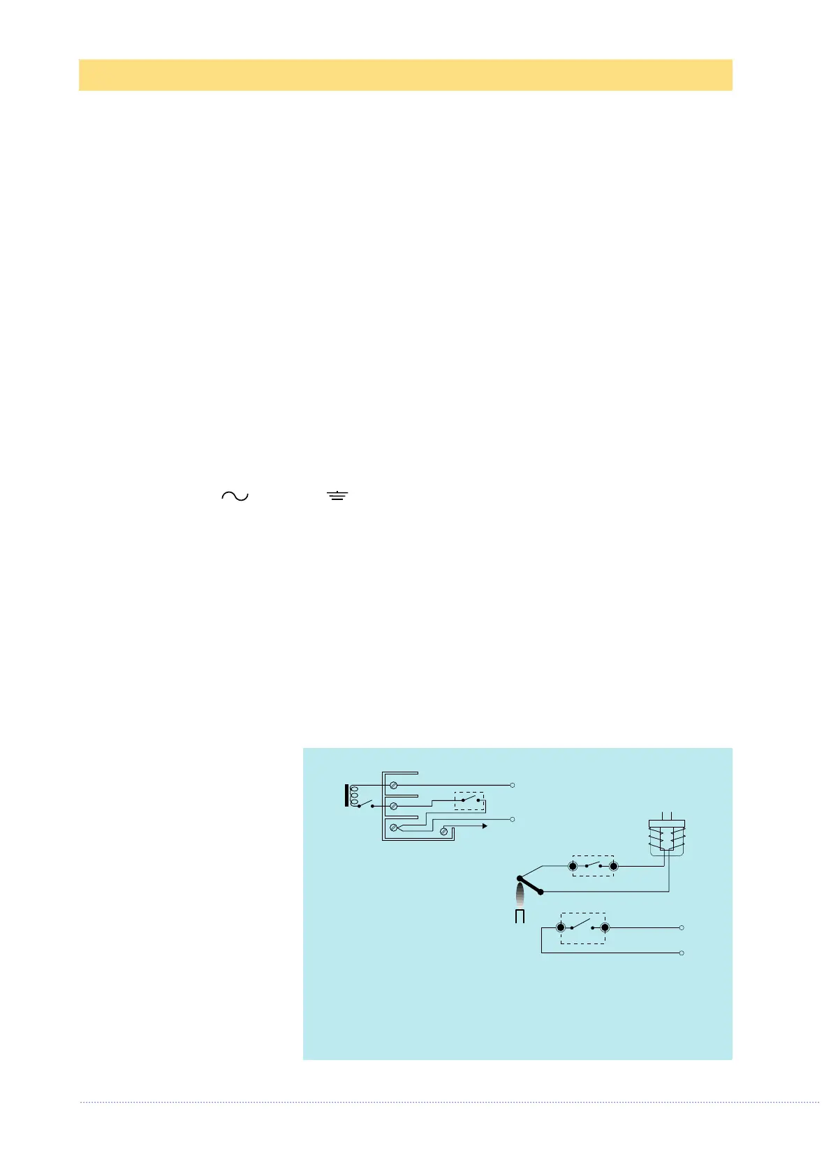
WIRING PLANS
w = Pilot burner electric ignition enabling
K = Internal enabling for main burner ignition
TA = Ambient thermostat
LS = Limit thermostat