17
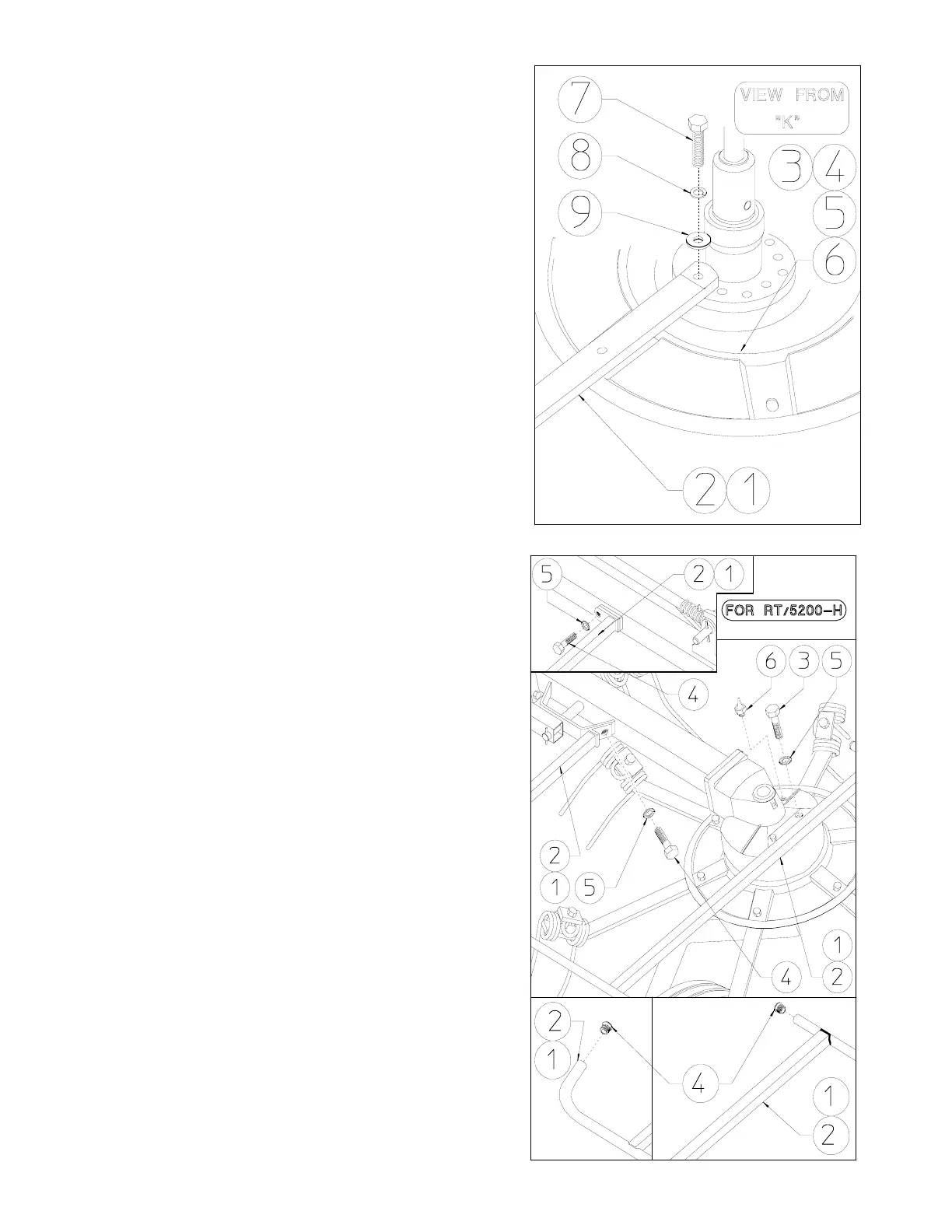
STEP “H”
(cont.d from previous page)
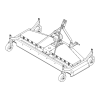
Attach the tine bars 1 (RH) and 2 (LH) to
their respective rotors 3-5 (RH) and 4-6
(LH) with screws 7, spring washers 8,
washers 8, screws 10 and nuts 11.
In this step, you will use:
Item 7 : 24 screws M12x30 (0.47”x1.18”)
Item 8 : 24 spring washers ø13 (ø0.51”)
Item 9 : 24 washers ø13 (ø0.51”)
Item 10 : 24 screws M12x35 (0.47”x1.38”)
Item 11 : 24 nuts M12
STEP “I”
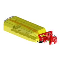
Attach the lateral guard 1 (RH) and 2 (LH) to
the machine body using the screws 3-4 and
washers 5. Attach the grease nipples 6 in the
proper holes.
In this step, you will use:
Item 3 : 4 screws M12x25 (0.47”x1”)
Item 4 : 4 screws M12x20 (0.47”x0.79”)
Item 5 : 8 washers ø13 (ø0.51”)
Item 6 : 2 grease nipples M10
STEP “L”
Apply caps 4 to lateral guard 1-2 (RH-LH)
In this step, you will use:
Item 4 : 4 caps ø27 (ø1.06”)