15
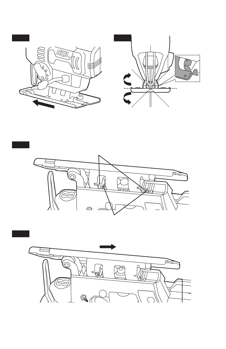
Move the foot slightly forward and tilt it to the required angle ( 0
o
or 45
o
) using the scale
(0°or 45°) that is marked on the base bracket. The foot has indents at 0
o
and 45
o
(tilt left or
right) for easy angle setting (Fig. 12 & Fig. 13).
Fig. 12
45º45º
0º
Fig. 13
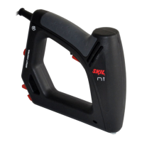
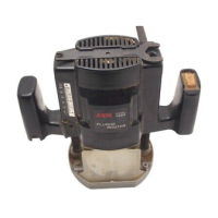
Move the foot slightly backward until the lock pins locate in the indents at 0
o
or 45
o
(Fig. 14 & Fig. 15).
Fig. 14
Indents
Lock Pins
Fig. 15
Make sure that the lock pins are situated in the indents at the angle you select. Pivot the bevel
lever back to lock the foot.