15/23
both stock sensors are active for the time in
parameter A13 activity stops.
Ejector IN – The input controls the ejector together
with the digital output OUT1, OUT2 (Chapter
8.12.).
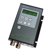
8.8. A20 Sensor 1 type
Type of sensor connected to input IN1.
Normal open (NO) - 24V is on the output of the
sensor if the supplied part is present.
Normal close (NC) - 24V is on the output of the
sensor if the supplied part is not present.
8.9. A21 Input IN2
Determining the use of digital input IN2. The setting
is identical as for input IN1 (Chapter 8.7.).
8.10. A22 Sensor 2 type
Determining the type of the sensor connected to
input IN2. The setting is identical as for input IN1
(Chapter 8.8.).
8.11. A23 Analogue AIN
Determining the use of analogue input AIN. It can be
configured as analogue 0-10V, or digital 0/24V.
Not used - The input is not used.
Amplitude - The input is configured as analogue. The
0-10V voltage is used to set the amplitude and
intensity of vibrations of the feeder from 5-100%
with 0.5% steps. The setting range can be
restricted by parameters A17, A18. The set value
is displayed in parameter A11.
JOG-min – The input is configured as digital. 24V
signal on the input causes the amplitude to
switch to the minimum value, which is determined
by parameter A18. Tip for you: Use this
setting if you need to decrease the speed of the
feeder during the activity. For example, when
pouring material on the scale when approaching
the desired weight.
Start – The input is configured as digital. The
supply of the +24V signal is the condition for