Page 8 of 40
2017-05-23
CU-M001 User manual
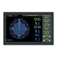
The screen presents speed through water (STW) used for the autopilot, radar and logged on the
voyage data recorder (VDR). The speed data can also be used for setting limits on the rudder and
stabilizer wings. It also shows speed over ground (SOG) used as a primary system for speed. Some
of this information is also available from the GPS systems. By adding an approved gyro heading
input into the system, together with parameters of the vessel, it is possible for the system to calculate
the transversal speed at any point of the vessel. This feature known as docking, allows the pilot to
be sure that both the fore and aft of the vessel are under tight control.
A speed log is a “Category B” equipment with no mandatory alarms. Alarm signals from “Category
B” equipments are called alerts. Alerts can be set on the speed, usually speed through water. These
are commonly used to warn the crew if the vessel is in danger of loosing rudder steerage, or if the
vessel is going over its recommended speeds.
The DL2 display does not have an internal inbuilt audible alarm. The audible alarm must be in the
external alarm system or from an optional external alert sounder.
In addition the system shows distance travelled through water and has a resettable daily trip counter.
This information is used for service intervals and navigation. Extra information is available regarding
the sea temperature and tilt of the vessel.
The user can operate the system via a touch screen or using an application on the conning unit.
The displays are intuitive and have a menu system, but also allows the user to click on the screen
to adjust the relevant parameters. Full setup, calibration and diagnostics are available from the
screens. Calibration is performed by a two leg sailing procedure, and once set, should not need
repeating unless the sensor is moved.
The system is low maintenance. After initial setup and calibration, the system requires no attention
except to change alert parameters if required. The sensor is exposed to the water and over time
some growth may appear. This can be carefully removed when possible, and is normally not a
problem except if the vessel is still for longer periods of time (weeks) in warm waters. The effect of
this growth is usually seen as the range of the bottom track being reduced.
The system has comprehensive built in test (BIT) that can be used to analyse the performance of the
equipment and give a warning if the data is not within specication. It also has inbuilt redundancy in
some areas, such that even if a failure occurs, it can still give some data. Due to the systems LAN
network point, it is possible to set up the system for remote diagnostics and upgrade using network.
In time this will help reduce service visits and increase the probability of rst time x.