DA 600 LPC • DA 600 • ECT 632-6 • DCT 632-6
1 Product description ....................................................................................................................................... 5
2 Product survey ............................................................................................................................................... 6
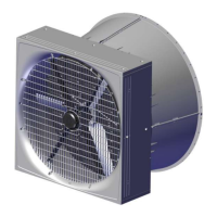
2.1 DA 600 LPC ................................................................................................................................ 6
2.2 LPC accessories ........................................................................................................................ 7
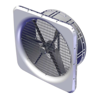
2.3 DA 600 ........................................................................................................................................ 8
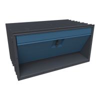
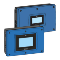
2.4 ECT/DCT 632-6 ........................................................................................................................... 9
3 Mounting guide............................................................................................................................................. 11
3.1 Recommended tools................................................................................................................ 11
3.2 Positioning of the fan in the exhaust unit ............................................................................. 12
3.3 Safety distance......................................................................................................................... 13
3.4 Position of motor controller/frequency converter ................................................................ 13
3.5 Mounting distances for the motor controller/frequency converter..................................... 13
3.6 Position of motor controller/frequency converter ................................................................ 14
4 Installation guide.......................................................................................................................................... 15
4.1 Electrical connection............................................................................................................... 15
4.1.1 Disclaimer at retrofitting fans ..................................................................................................... 15
4.1.2 Mains supply dimensioning regarding harmonic distortion ........................................................ 15
4.1.3 Cabling in the exhaust unit......................................................................................................... 15
4.1.4 Cabling into the motor controller/frequency converter ............................................................... 16
4.2 Connection in the LPC motor controller/frequency converter ............................................ 17
4.2.1 Terminals for power supply........................................................................................................ 18
4.2.2 Terminals for supply of the fan motor ........................................................................................ 19
4.2.3 Signal terminals ......................................................................................................................... 19
4.2.4 Terminals on relay module......................................................................................................... 20
4.3 LED indication on the motor controller/frequency converter.............................................. 21
4.4 Alarms....................................................................................................................................... 21
4.5 Adjusting the jumper and connecting the shutter................................................................ 22
4.6 General information about circuit diagrams ......................................................................... 23
4.6.1 Color code.................................................................................................................................. 23
4.6.2 Power supply isolator................................................................................................................. 23
4.6.3 Letter code ................................................................................................................................. 23
4.7 Cable Plans and Circuit Diagrams ......................................................................................... 24
4.7.1 Circuit diagrams for OFF/AUTO/ON switch ............................................................................... 24
4.7.1.1 Control voltage (LPC with DA 74CO)......................................................................................... 24
4.7.1.2 Control voltage (LPC with DA 74CV) ......................................................................................... 25
4.7.1.3 Control voltage (ON/OFF with DA 74CO) .................................................................................. 26
4.7.2 DA 600 LPC-2 ........................................................................................................................... 27
4.7.2.1 Cable plan.................................................................................................................................. 27
4.7.2.2 Terminals in LPC 230 V fan ....................................................................................................... 27
4.7.2.3 Circuit diagram........................................................................................................................... 28
4.7.3 DA 600 LPC 230 V with DA 74CO ON/OFF ............................................................................. 29
4.7.3.1 Cable plan.................................................................................................................................. 29
4.7.3.2 Terminals in LPC 230 V fan ....................................................................................................... 29
4.7.3.3 Terminals in DA 74CO ............................................................................................................... 30
4.7.3.4 Circuit diagram .......................................................................................................................... 30
4.7.4 DA 600 LPC 230 V with thermal cutout and DA 74CO ON/OFF .............................................. 31
4.7.4.1 Cable plan.................................................................................................................................. 31
4.7.4.2 Terminals in LPC 230 V fan with thermal cutout........................................................................ 31
4.7.4.3 Terminals in DA 74CO ............................................................................................................... 32
4.7.4.4 Circuit diagram .......................................................................................................................... 32
4.7.5 DA 600 LPC 230 V with DA 74CV stepless .............................................................................. 33
4.7.5.1 Cable plan.................................................................................................................................. 33
4.7.5.2 Terminals in LPC 230 V fan ....................................................................................................... 33
Technical User Guide
 Loading...