7
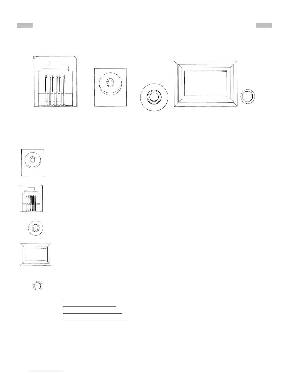
2.1 Control Panel
The control panel of the AZGTi mount is shown below:
2.2 Panel Interface Components:
PART II : ELECTRONIC CONTROL INTERFACE
POWER: This is an input for external power to avoid running on the 8 AA batteries
in the AZGTi mount battery compartment.
HAND CONTROL: This RJ-12 6-pins outlet is for connecting the SynScan hand
controller.
SNAP:This is a stereo jack outlet to connect with a camera’s shutter control port.
The SynScan hand control can control the camera to take pictures automatically
via this interface.
ON/OFF Switch: Turns the power to the mount and hand controller on and o.
Power LED: The power LED serves as a power-on indicator and provides other
statuses.
1. Steady on: Internal Wi-Fi is o.
2. Intermittent one ash: Internal Wi-Fi is on.
3. Intermittent two ashes: App has connected to internal Wi-Fi.
4. Intermittent three ashes: Internal control board has entered rmware update
mode.
Hand Control
Power
SNAP
ON OFF
LED
Fig. 2.1