(2) Opening /clos ing delay sett ing
(D ef au lt : M OT2 g ea rmo to r wi ll op en fir st ).
4 ON= MO T2 ge ar mot o r w il l o pe n fi rs t
4 OFF = MOT 1 g ea rm ot or wi ll op en f ir st
MOT 2 open first
(3) Singl e gate l eaf o peration sett ing
5 ON= On l y MO T1 ge ar mot o r i s a va l ia ble
5 OFF = Bot h MOT 1 a nd MOT 2 g ea rm ot or s a re a va li ab le
MOT 1 only
(4) Operati on mode s et ting
6 ON= T he operat ion mode is : OPEN-
CLOSE- OPEN
6 OFF= The opera ti on mode is:
OPEN-STOP- CLOSE-STOP- OPEN
OPEN -
CLOSE
-
O PEN
(5) Auto closin g s et ting:
7 ON= T he un it c an no t r ec ei ve a ny op er at in g commands
b ef or e a ut om at ic all y c lo si ng.
7 OFF = Th e u ni t ca n r ec ei ve op er ati ng co mma nd s b ef ore au
t oma ti c al ly cl os i ng.
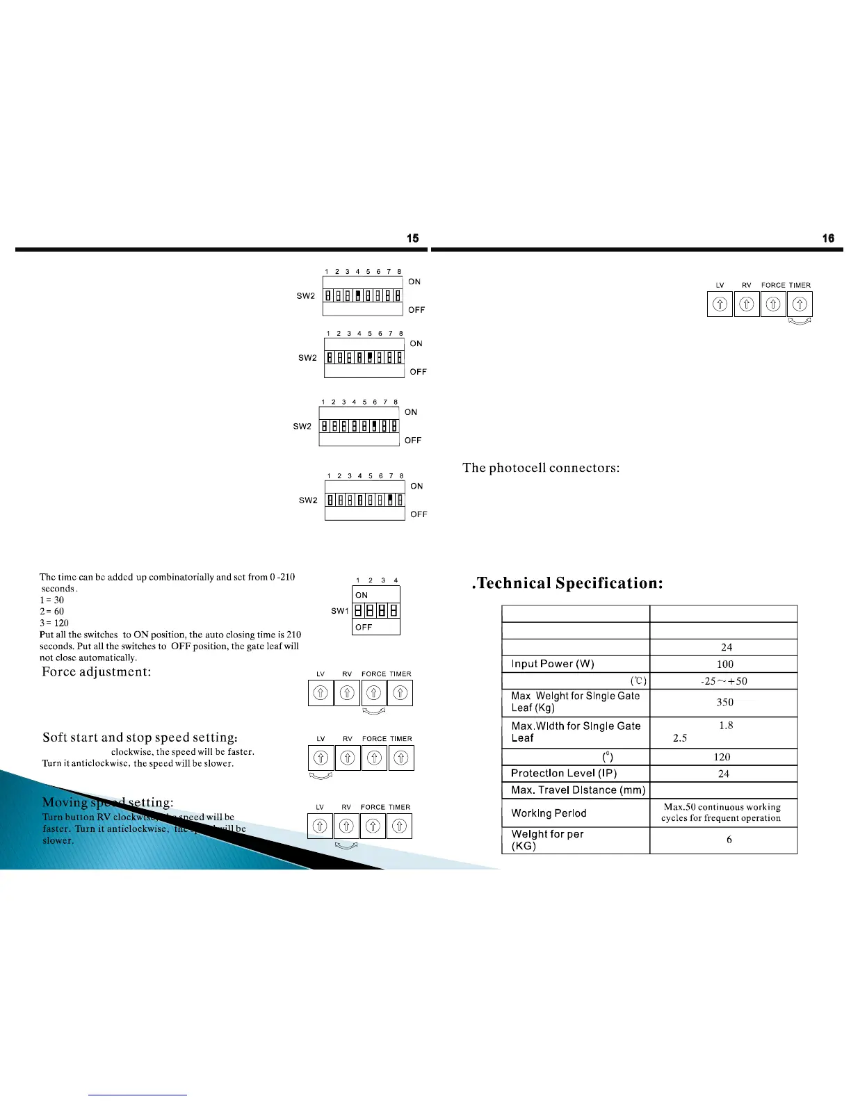
Auto closing time setting:(Th is fun tion is s et OFF in
factory ).
s
s
s
(6)
Tur n b utt on FO RCE c loc kwise, the driving f orce will
bec ome s tr onger. Tur n it ant iclockwise, t he dr iving
f or ce will be come weaker.
Weaker Str onger
(7)
Tur n b utt on LV
Slow er
Fast er
(8)
Slow er Fast er
(9) Operati ng tim e setti ng:
Tu rn bu tt on T IM ER c l oc kwi s e, th e o pe ra ti n g t im e
wil l b e l on ge r;
Tu rn bu tt on T IM ER a nti cl oc kw is e, t he op er at in g
t im e wil l b e s ho r te r;
Th e ti me ca n b e s et fr o m Ma x. 63 S t o M in . 30S
S horter L onger
(10) Elect ric l ock(opt ional)
LO CK an d – ar e conne ct ors f or e le ctri c lo ck , F-600 (1 2V/DC-A) an d F -6 00(1 2V /DC-B)
ma tch wit h 12V/ 500mA el ctr ic lock ; F -6 00(2 4V /D C- A) ma tche s w it h 24V/5 00 mA
el e ctri c l o ck. Whe n the el ect ric l oc k is co nn ecte d, i t w ill open befo re the g at e le af opens.
(11) The wired cont ro l connectors( Key switch)
DOOR1, - and DOOR 2 ar e the c onnectors f or wired control( for normal open only.)
When DOOR1 and – are connected, only MOT1 gearmotor will wor k and DL5 LE D will turn
on; When DOOR2 and – are connected, both gear motors will wor k and DL4 LE D will turn on.
(12)
The connect or s for phot ocell are normal closed.I f the cont rol unit is installed wit hout
photocell, connect t erminals IR1 , IR2 and- with a s hort cable, othewise the unit will
not be operat ed( these 3 connectors have been connected in fact or y). If only IR1 is used,
please connect IR2 and ter minals wit h a short cable. When the beam of photocell
IR1 is int errupted by obst ac les, the gate leaf will st op and r evers e. DL2 LED on the main
panel will turn off . I f only IR2 is used, connect IR1 and- with a short cable.
When the beam of infrar ed IR2 is interrupted by obst acles , t he gate leaf will s top. DL3
LED on t he main panel will turn of f .
10
F-600
220~240 Vac @ 50/60Hz
Model
Working power ( vac )
Ambient temperature range
.
(m)
Max. Open Angle
(with electr ic lock)
320
Gearmotor
Motor voltage ( vdc )
 Loading...