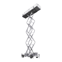
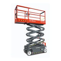
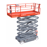
The Skyjack SJ-600, SJ-800, and SJ-1000 Series Work Platform is a highly maneuverable, mobile work station designed to transport and raise personnel, tools, and materials to overhead work areas. It is crucial for operators to read and fully understand the safety panel labels and all warnings in the manual and on the work platform before operation. Any modifications from the original design are strictly forbidden without written permission from Skyjack, Inc.
The work platform consists of three major assemblies: the platform, the lifting mechanism, and the base. An operator's control box is mounted on the platform railing, while auxiliary and emergency controls are located at the base.
The platform features a tubular support frame, a skid-resistant "diamond plate" deck surface, and 43-1/2" (1.10m) hinged railings with 6" (15.24cm) toe boards and mid-rails. Entry to the platform is via a spring-returned gate, located on either side for 800 & 1000 Series models, and from the rear for 600 Series models. The 600 Series can be equipped with a front extension platform, while the 800 & 1000 Series can have front or both front and rear extension platforms.
Lifting Mechanism:
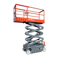
This mechanism is constructed from formed steel sections, forming a scissor-type assembly. It is raised and lowered by single-acting hydraulic lift cylinders equipped with holding valves. A two-section pump, driven by an engine, provides hydraulic power to the lift cylinders. A safety bar, located inside the lifting mechanism, can be properly positioned to prevent the scissor-type assembly from lowering during maintenance or repairs.
Base (600 & 800 Series):
The base is a rigid one-piece weldment supporting two side cabinets. One cabinet houses hydraulic components, up/down controls, electrical components, and the starter battery. The other cabinet contains the fuel tank, hydraulic tank, and LP tank (SJ 800). The propane tank on the SJ 600 series is located either behind the access ladder or the fuel cabinet. The front axle has two wheels, steerable by a hydraulic cylinder, and can be non-driven (2WD models) or drive shaft/gear box driven (4WD models). The rear axle is drive shaft/gear box driven and features a spring-applied, hydraulically-released disc parking brake. A slide-out drawer at the front of the base supports an engine coupled with a two-section hydraulic pump. An engine control panel is also located at the front.
Base (1000 Series):
Similar to the 600 & 800 Series, the 1000 Series base is a rigid one-piece weldment with two side cabinets. One cabinet contains the hydraulic tank, hydraulic components, up/down controls, electrical components, emergency lowering battery, and starter battery. The other cabinet contains the fuel tank and LP tank (if equipped). The front axle has two wheels, steerable by a hydraulic cylinder, and can be non-driven (2WD models) or drive shaft/gear box driven (4WD models). The rear axle is drive shaft/gear box driven and features two spring-applied, hydraulically-released parking brakes. A slide-out drawer at the front of the base supports an engine coupled with a two-section hydraulic pump. An engine control panel is also located at the front.
Operator's Control Box:
This removable control box is mounted at the right front of the platform and contains controls for engine operation, work platform motion, and emergency stopping.
Hydraulic Outriggers (Optional):
Optional hydraulic outriggers are mounted to the four corners of the base. Controls on the operator's control box are used to extend and retract the hydraulic outrigger cylinders.
Operating Controls Identification:
The manual provides detailed descriptions for identifying, explaining, and locating all operating controls. A qualified operator must read and fully understand these descriptions before operating the work platform. Both standard and optional controls are identified.
Base Controls - Electrical Panel:
Located in the Hydraulic/Electric Side Cabinet, this panel includes:
- Up Push-Button Switch: Raises the platform.
- Down Push-Button Switch: Lowers the platform.
- Hour Meter: Records engine running time.
- 20 Amp Circuit Breaker Resets: Pops out in case of power overload or positive circuit grounding.
Emergency Battery Disconnect Switch:
Located at the front of the Hydraulic/Electric Side Cabinet, this switch disconnects power to all circuits when in the "OFF" position. It must be in the "ON" position for any circuit to operate.
Engine Control Panel (Dual Fuel - Ford Gasoline Engine):
Attached to the Engine Roll-out at the front of the base, this panel includes:
- Engine Off/On Switch: A plunger-type switch that, when pulled out, energizes the engine circuit and the operator's control box. Pushing it in stops the engine.
- Fuel Select Switch: Used to switch between LP GAS and gasoline.
- Engine Start Push-Button: Energizes the engine starter motor.
- Engine Choke Push-Button: Sets the choke for starting a cold gasoline/propane engine.
Engine Control Panel (Diesel - Kubota Diesel Engine):
Attached to the Engine Roll-out at the front of the base, this panel includes:
- Engine Off/On Switch: A plunger-type switch that, when pulled out, energizes the engine circuit and the operator's control box. Pushing it in stops the engine.
- Engine Start Push-Button: Energizes the engine starter motor.
- Engine Glow Plug Push-Button: Energizes the glow plug to aid in starting a cold diesel engine.
- Glow Plug Indicator Light: Illuminates until glow plugs complete their timed heating cycle, indicating the engine is ready to start when it goes out.
Base Control Box/Station (CE):
Located on the rear of the hydraulic/electric cabinet or base, this station contains:
- Platform/Base Select Key Switch: Directs power to the operator's control box ("PLATFORM" position) or the base control box/station ("BASE" position).
- Platform Up/Down Selector Switch: A toggle switch to raise or lower the platform.
- Emergency Stop Button: A red "mushroom-head" button switch designed to disengage power to the platform controls.
- Powered Platform Emergency Retraction Push-button: Activates the platform retraction system in case of electrical system failure or emergency.
1500W AC Inverter (Option):
Located on the base of the machine, it has:
- ON/OFF Switch: Activates or terminates inverter function.
- Status LEDs: Indicate operating or fault status.
- 15 Amp Circuit Breaker: Pops out in case of power overload or circuit grounding.
- GFCI Outlet: Provides AC power during inverter operation.
This metal control station is mounted at the right front of the platform and includes:
- Torque Toggle Switch: Cuts out High Range and 3rd speed for maximum torque when climbing grades or in rough terrain. All three speeds are available in the other position.
- Operator Horn Push-Button: Sounds an automotive-type horn.
- Engine Choke Push-Button (Dual fuel engines): Sets choke for starting a cold gasoline engine.
Glow Plug Push-Button (Diesel Engines): Powers the glow plug for starting cold diesel engines.
- Engine Start Push-Button: Energizes the engine starter motor.
- Enable Push-Button: When depressed and held, brings power to the lift or outrigger circuits.
- Emergency Stop Button: Disconnects power to the control circuit when struck.
- Off/Lift/Drive Select Key Switch: "OFF" disconnects power. "LIFT" brings power to the Lift Enable Push-button. "DRIVE" brings power to the Drive/Steer Controller.
- Up/Down Selector Switch: Raises or lowers the platform.
- Platform Power Indicator Light: Glows when key switch is in "LIFT" or "DRIVE" position.
- Low/High Throttle Select Switch: Allows selection between high and low engine throttle speeds.
- Low/High Range Select Switch: Selects "LOW" range (high torque) or "HIGH" range (high speed).
- Drive/Steer Controller: A one-hand toggle lever for steer and three-speed drive motion, returning to neutral when released ("deadman" control).
- Drive Enable Switch: A momentary "Trigger" style switch that energizes the drive/steer controller and must be held continuously during drive or steer functions.
Outrigger Controls (Option - Model 9250A, 7135 & 800 Series):
Located on the Operator's Control Box, these switches control each outrigger's extension and retraction.
- Outrigger Up/Down Control Toggle Switches: Control the extension and retraction of each individual outrigger.
Hydraulic Generator Control (Option):
Located on the side of the Operator's Control Box or Auxiliary Control Box console, this push-button switch starts the hydraulic generator on the base.
- Hydraulic generator Off/On Push-Button Switch: Illuminates when activated, starting the base-mounted generator.
- Hydraulic generator Off/On Toggle Switch: Starts and stops the base-mounted generator.
This metal control station is mounted at the right front of the extension platform and contains:
- Enable Switch: Brings power to the Platform Extend/Retract Switch when activated.
- Platform Extend/Retract Switch: Extends/retracts the powered extension platform.
Identification And Operation of Safety Devices:
Fold-Down Guardrail System:
This system reduces the shut height of the work platform for transporting and traveling through doorways.
- Guardrail Locking Pin W/Lanyard: To fold down, remove the locking pin at each pivot point and lower each guardrail. To raise, swing up and lock in place, ensuring the detent ball of each pin is clear of the side of the pivot brackets. The guardrail system MUST be upright and locked in place before resuming normal operation.
Base Controls - Manual Safety Bar:
- Safety Bar: Designed to support the scissors assembly (when properly positioned) for inspection and maintenance. To lower, push the lock lever rearward. Follow the procedure on the safety bar decal. DO NOT reach through the scissor assembly without the safety bar properly positioned to avoid crushing hazards.
Operating Procedures - Set-Up Procedure:
- Remove packing materials and inspect for transport damage.
- Inspect the work platform thoroughly and remove foreign objects.
- Raise and lock side, extension platform (if equipped), and gate railings.
- Remove the operator's control box from its shipping container and secure it to the railing. Attach control and power deck extension cables.
- Open the fuel tank side cabinet door. Fill the fuel tank to "F" level.
- Close the fuel tank side cabinet door.
- For Dual Fuel machines, ensure the propane hose coupler is secured and the valve is open.
- Open the hydraulic tank side cabinet door. Check the hydraulic oil level (scissors fully lowered) in the tank; it should be at or slightly above the top mark on the sight glass. Add quality grade hydraulic oil if needed.
- Check battery fluid level. Add distilled or demineralized water if not at the FULL mark.
- Move the work platform to a level, firm test area for vertical extension. If pushing, towing, or winching, ensure the parking brake is disengaged and DO NOT exceed 2 mph (3.2 kph).
Using the Base Controls:
- Turn the Emergency Power Disconnect Switch to "ON."
- Pull out the Emergency Stop Button (engine will not start unless this is "ON").
- Insert the key into the Off/Lift/Drive Select Key Switch and turn to "LIFT" position. Start the engine in low throttle position.
Using the Engine Controls on the Engine:
- Pull the Engine Off/On Switch plunger out.
- Select the desired fuel source with the Fuel Select Switch (Gasoline engines with dual fuel). Refer to the label inside the engine front guard for the fuel switch sequence.
- Depress and hold the Choke Push-Button (Gasoline engines) or Glow Plug Push-Button (Diesel engines) for 15 to 20 seconds.
Operating Procedures - Prestart Checks:
- Read and understand all of Section 2, OPERATION, and all warnings/instruction decals.
- Check for obstacles around the work platform and in the path of travel.
- Check overhead clearances.
- Ensure all guardrails are in place and locked.
Operator's Checklist (Daily or at Beginning of Each Shift):
Inspect and/or test:
- Operating and emergency controls.
- Safety devices and limit switches.
- Personal protective devices.
- Tires and wheels.
- Outriggers (if equipped) and other structures.
- Air, hydraulic, and fuel system(s) for leaks.
- Loose or missing parts.
- Cables and wiring harnesses.
- Placards, warnings, control markings, and operating manuals.
- Guardrail system, including locking pins.
- Engine oil level (if so equipped).
- Battery fluid level.
- Hydraulic reservoir level.
- Coolant level (if so equipped).
- Parking brake (check operation).
Operator Qualifications:
Only trained and authorized persons should use this work platform. Operators MUST understand limitations, warnings, operating procedures, and responsibilities for maintenance. They must be familiar with the operating manual, warnings, and instructions, and all warnings on the work platform. Operators MUST also be familiar with employer's work rules, government regulations, and demonstrate ability to understand and operate the machine in the presence of a qualified person.
Start and Operation - Using the Base Controls:
- Turn Emergency Power Disconnect Switch to "ON." For CE units, ensure the base control emergency stop button is "ON."
Using the Engine Controls on the Engine:
- Pull the Engine Off/On Switch plunger out.
- Select the desired fuel source with the Fuel Select Switch (Gasoline engines with Dual Fuel).
- Use the ladder to access the platform deck. Close and latch the gate.
- Pull out the Emergency Stop Button.
- Insert the key into the Off/Lift/Drive Select Key Switch, then select "LIFT" or "DRIVE." Select "LOW" position with the HI/LOW Throttle Select Switch.
- If the engine is cold, depress and hold the Engine Choke Push-button (Gasoline engines) or Glow Plug Push-button (Diesel engines) for 15 to 20 seconds, then release.
- Depress and hold the Engine Start Push-Button until the engine starts, then release. DO NOT over crank the starter.
- Select "HIGH" position with the Low/High Throttle Select Switch.
- To Raise the Platform: Ensure the emergency stop button is pulled out. Select "LIFT" position with the Off/Lift/Drive Select Key Switch. Depress and hold the Enable Push-button, then select "Up" position with the Up/Down Selector Switch. Release the switch to stop.
- To Lower the Platform: Ensure the emergency stop button is pulled out. Select "LIFT" position with the Off/Lift/Drive Select Key Switch. Depress and hold the Enable Push-button, then select "Down" position with the Up/Down Selector Switch. Release the switch to stop. A warning alarm will sound while lowering.
- If High Torque is Desired: Select "LOW" position with the Low/High Range Select Switch. Select "LOW" range when climbing grades, traveling in rough terrain, or loading/unloading.
If High Speed is Desired: Select "HIGH" position with the Low/High Range Select Switch. Select "HIGH" range when traveling on a hard, level surface with the platform fully lowered.
- To Drive Forward or in Reverse:
- Ensure the emergency stop button is pulled out. Select "DRIVE" position with the Lift/Off/Drive Key Switch.
- Activate and hold the Drive Enable trigger switch (squeeze towards the joystick).
- Push or pull the controller handle forward or backward for desired speed and direction.
- Return the joystick to the neutral center position to stop. Release the Enable trigger switch.
- To Steer: Select "DRIVE" position with Off/Lift/Drive Select Key Switch. Activate and hold the Drive Enable trigger switch, then press the rocker switch on top of the Drive/Steer Controller handle in the desired direction.
- To Climb a Grade: Select the appropriate position with the Torque Toggle Switch. The machine MUST be in a fully retracted position.
- To extend/retract a manual extension platform: Remove retaining locking pins, then push/pull the extension platform using the push bar until the desired extension is reached. Reinsert locking pins to prevent accidental movement.
- To extend/retract a hydraulic powered extension platform: Turn key to "LIFT" position with Off/Lift/Drive Select Key Switch, activate the Enable Switch, then push the extension/retraction toggle switch to the "Up" position until desired extension is reached. Release switch to stop. To retract, push the toggle switch to the "Retract" position.
- To switch from LP GAS to gasoline: Move the fuel selector switch on the engine control panel to "GASOLINE." To shut off fuel, move the switch to "OFF."
To switch from gasoline to LP GAS: With the engine running, move the switch to "OFF" and let the engine run until gasoline is exhausted. When the engine stops, move the switch to "LP GAS" and restart. Ensure the LP GAS valve is ON when switching to LP GAS and OFF when switching from LP GAS to gasoline.
Shutdown Procedure:
- Completely lower the platform.
- Turn the key to "OFF" position and remove it from the Off/Lift/Drive Select Key Switch in the control box.
- Push Emergency Stop Button(s) in.
- Turn the Emergency Power Disconnect Switch to "OFF" position. For CE units, remove the key, then push in the Emergency Stop Button on the base control box.
Emergency Lowering System (600 & 800 Series):
This system allows platform lowering in an emergency or electrical system failure.
- Holding Valve Manual Override Knob: Red knurled knobs at the bottom of each lift cylinder, when depressed and turned counter-clockwise, bypass the holding valve. They MUST be depressed and turned clockwise to restore normal operation. An access rod is provided for CE units.
- Emergency Lowering Valve: Pull out and hold the plunger, and the platform will gradually lower. Located at the rear of the hydraulic/electric side cabinet. Use in conjunction with holding valve manual overrides.
Emergency Lowering System (1000 Series only):
Located on the hydraulic tank and accessed through a hole in the hydraulic/electric cabinet door, this system uses an auxiliary battery to power a push-button switch that activates a lowering valve on the base of each lift cylinder.
- Emergency Lowering Push-Button Switch (1) and Emergency Lowering Valve (2): To lower the platform, depress and hold the red push-button switch, then pull the valve plunger out. The platform will gradually lower. Release the valve plunger to stop. Keep clear of the scissors mechanism when using the emergency lowering valve. After lowering, the red knurled knobs on each holding valve MUST be depressed and turned clockwise to restore normal operation.
Outrigger Operating Procedures:
A. Before Operation:
- Check overhead clearances and ground obstructions.
- Check that the platform is fully lowered (outrigger controls are cut out when the platform is raised).
- Check that supporting surfaces under tires and outrigger pads are firm and capable of supporting the machine and load. DO NOT place outrigger pads on street drains, manhole covers, or other supported surfaces.
B. Operation - Extending The Outriggers:
- Rotate Key Switch to "LIFT" position.
- Depress and hold the Enable Push-button, then push and hold each Outrigger Up/Down Toggle Switch to "DOWN" position to obtain firm ground contact.
- Check outrigger pad contact surface and make adjustments.
- Again, depress and hold the Enable Push-button, then push and hold each Outrigger Up/Down Toggle Switch to "DOWN" position until the machine is completely supported by the outriggers.
- Level the machine. AGAIN, CHECK THE OUTRIGGER PAD CONTACT SURFACE!
- To raise the platform, press and hold the Enable Push-Button, then rotate the Up/Down Selector Switch to the "Up" position.
C. Operation - Retracting The Outriggers:
- Fully lower the platform.
- Depress and hold the Enable Push-button, then push and hold pairs (front or rear) of Outrigger Up/Down Toggle Switches to "UP" position until the outriggers are fully retracted. Cut out switches protect outriggers from damage. If the machine will not drive, visually check that ALL outriggers are fully retracted.
D. During Operation:
- If an alarm sounds, the platform is not level. LOWER THE PLATFORM IMMEDIATELY and make necessary adjustments.
Hydraulic Generator (Option):
For models with generator controls on the main control box:
- To start, ensure the engine is on high throttle ("HIGH" on Low/High Throttle Select switch). Select "LIFT" position with the Off/Lift/Drive key switch, then depress the hydraulic generator push-button on the side of the operator's control box. The button will illuminate, and the generator on the base will start. To restore normal operation, depress the push-button again. The light will go out, and the generator will turn off. While the hydraulic generator push-button switch light is illuminated, the lift and drive circuits in the Operator's Control Box are cut out.
For models with generator controls on the auxiliary or optional control box:
- To start, select "LIFT" position with the Off/Lift/Drive key switch. With the engine running, flip the hydraulic generator toggle on the auxiliary control box to the energized position. The engine will automatically switch to high throttle, and the generator on the base will start. To restore normal operation, flip the toggle switch to the "OFF" position. The generator will turn off. Activating any lift or outrigger functions will disable the generator. Changing the keyswitch setting, activating the emergency stop, or an engine stall will also stop generator function. The platform may be lowered during generator operation.
Electrical Inverter (Option):
- Turn the main disconnect switch to "ON."
- Turn the "ON/OFF" switch on the front face of the inverter to "ON." Inverter activation is indicated by a glowing green LED. To turn off, shut down the platform engine and/or slide the "ON/OFF" switch on the inverter to "OFF." The inverter only supplies power when the engine is running and the throttle switch is set to the HIGH idle position. Deselecting high idle throttle or stopping the engine will turn the inverter off.
Winching and Towing Procedures (600 & 800 Series):
When towing, DO NOT drive onto a downward slope or brake the towing vehicle rapidly.
Parking Brake System:
- Parking Brake Disc: This device disengages the brake disc when driving forward or in reverse. A hydraulic brake cylinder, linked to a disc caliper, engages and disengages a brake disc on the rear axle drive shaft yoke. The brake MUST be manually disengaged for pushing, towing, or winching. DO NOT push or tow the work platform onto a downward slope or pull it down an incline towards the winch.
Preparation for Winching Or Towing:
- Make sure the work platform is on level ground. Chock or block the wheels.
- Turn the Emergency Power Disconnect Switch to "OFF."
- Depress the black plunger on the Brake Valve until it stays in.
- Grasp the red hand pump plunger and rapidly depress 60 to 80 times until firm resistance is felt. The brake is now released.
- Remove wheel chocks or blocks, then push, tow, or winch the work platform to the desired location. DO NOT exceed 2 mph (3.2 km/h). DO NOT push or tow the platform onto a downward slope or pull it down an incline towards the winch.
- Position the machine on a firm and level surface. Chock or block the wheels or re-engage the parking brake by momentarily activating the drive function. The parking brake will reset automatically when the work platform is put back into service.
Winching And Towing Procedures (1000 Series only):
When towing, DO NOT drive onto a downward slope or brake the towing vehicle rapidly. DO NOT manually disengage the parking brakes if the work platform is on a slope.
Parking Brake System:
- Parking Brake: This spring-applied, hydraulically-released parking brake is automatic. Pins retract and extend by single-acting hydraulic cylinders, engaging brake discs on the rear wheels when lifting, lowering, parking, and steering. Pins disengage when driving. The brake pins MUST be manually disengaged for pushing, towing, or winching. DO NOT push or tow the work platform onto a downward slope or pull it down an incline towards the winch.
Preparation for Winching Or Towing:
- Turn the Emergency Power Disconnect Switch to "OFF." Make sure the work platform is on level ground.
- Chock or block the wheels to prevent rolling.
- For Left-Hand Brake: Using a 3/4" wrench, rotate the block on the brake pin 90° clockwise. The brake pin should be clear of the brake disc.
For Right-Hand Brake: Using a 3/4" wrench, rotate the block on the brake pin 90° counterclockwise. The brake pin should be clear of the brake disc.
- Remove wheel chocks or blocks, then push, tow, or winch the work platform to the desired location. DO NOT exceed 2 mph (3.2 km/h). DO NOT push or tow the platform onto a downward slope or pull it down an incline towards the winch.
- Position the machine on a firm level surface. Chock or block the wheels or re-engage the parking brake by momentarily activating the drive function. The parking brakes will reset automatically when the work platform is put back into service.
Maintenance And Inspection Schedule:
The manual includes a detailed schedule for daily, weekly, monthly, 3-month, 6-month, and 12-month inspections and maintenance tasks, covering engine, mechanical, electrical, hydraulic, and miscellaneous components. Tasks include visually inspecting, checking operation, tightness, relief valve settings, lubricating, replacing, checking oil levels, checking noise levels, and ensuring manuals are in the box. Specific requirements for gear oil are also provided.