Page 46 December 2007
Rough Terrain Scissors
Component Identification (Special Options) Section 3 - Operation
3.6 Component Identification (Optional
Equipment/Attachments)
This following descriptions are for identification,
explanation and locating purposes only of optional
equipment.
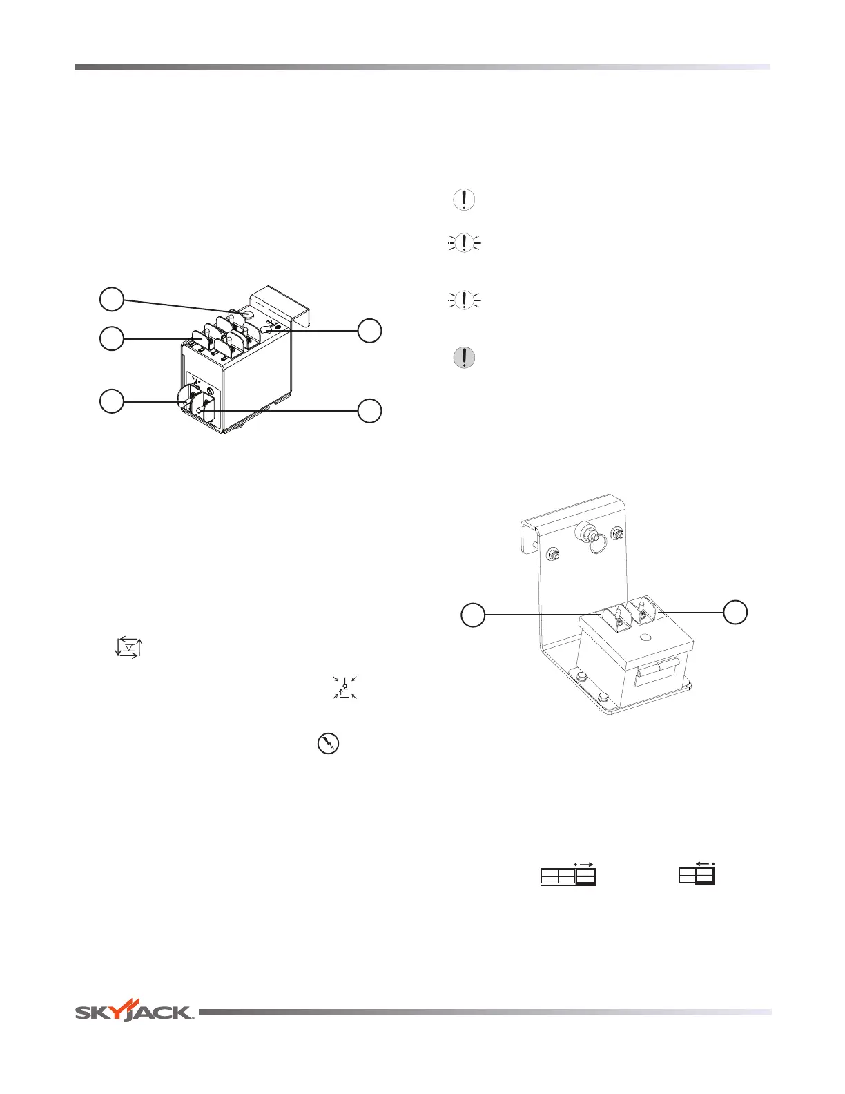
3.6-1 Generator/Outrigger Control Console (If
Equipped)
The outrigger control console are located next to the
platform control console. These switches control the
outriggers’ extension and retraction.
5
1
2
4
3
Figure 3-6. Outrigger Controls with All Options on
Auxiliary Control Console
1. Generator Switch - This switch activates the
generator.
2. Outrigger Extend/Retract Switches - These
switches control the extension and retraction of
each individual outrigger.
3. Auto-Level Switch - When this switch is in the
“
“ extend position, each outrigger will extend
and automatically adjust until the aerial platform
is level. When the switch is in the “
” retract
position, the outriggers will retract.
4. Outrigger Enable Switch - This “ ” outrigger
enable switch, when in the extend or retract
position, activates the functions on the auto-
level switch and the outrigger extend/retract
switches.
5. Leveling Indicator Light - This light functions
when the auto and manual level functions are in
use and illuminates to display the status of the
auto-leveling outriggers. The indicator light has
the following states:
Off: The outriggers are fully retracted.
Flashing Rapidly: The outriggers are extending
or retracting.
Flashing: Not all outrigger legs have firm
ground contact or aerial platform is not level.
On: The outriggers are extended and the
platform is level.
3.6-2 Powered Extension Control Console (If
Equipped)
This control console is mounted on one of the
extension platform guardrails. It contains the following
controls:
2
1
Figure 3-7. Powered Extension Control Console
1. Enable Switch - This switch, when activated and
held, allows the extension platform extend/retract
switch functions to operate.
2. Extend/Retract Switch - This switch, when
activated, “ ” extends or “ ” retracts
the powered extension platform. Refer to
Section 3.8-9 on how to extend/retract the powered
extension platform.