3
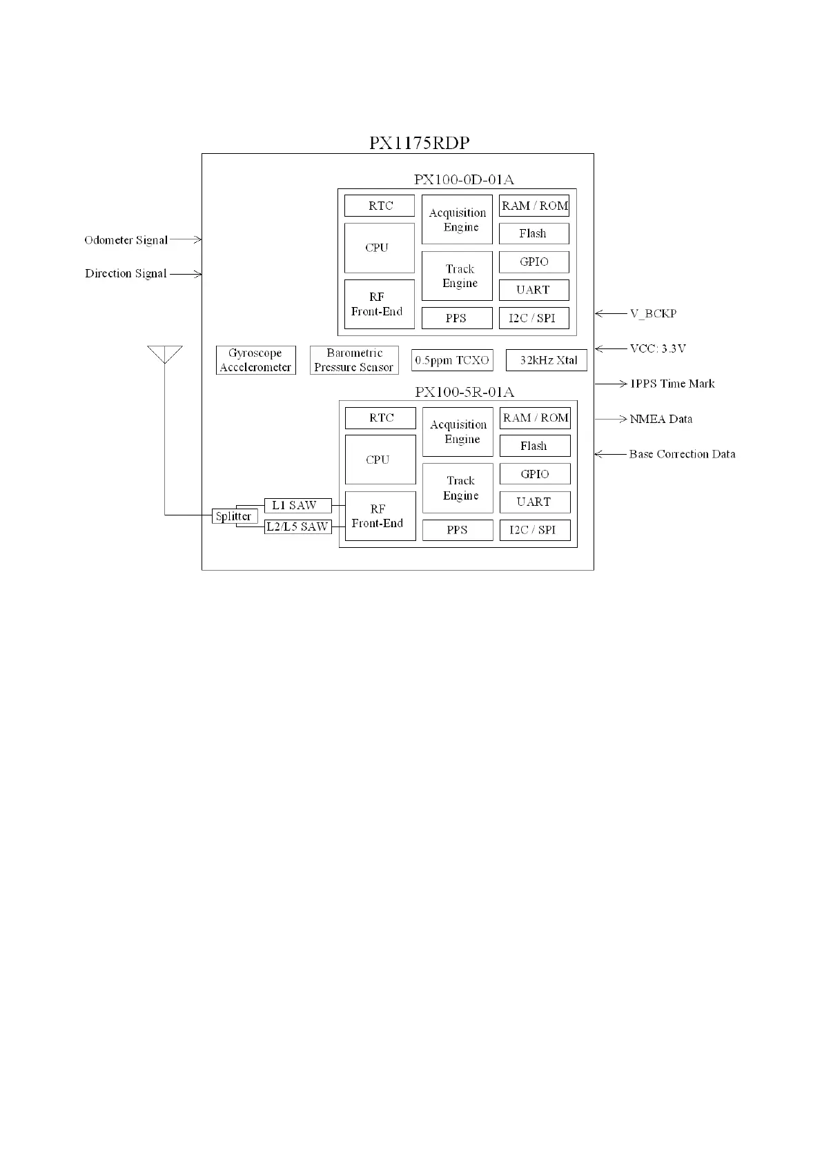
BLOCK DIAGRAM
Module block schematic
Active antenna is required to use with PX1175RDP. The received signal goes through a signal
splitter, to individual L1 and L2/L5 SAW filters to remove out-band interference, then to the
PX100-5R-01A GNSS receiver chip for RTK signal processing. Using correction data from an RTK
base station, the PX1175RDP computes the antenna position to centimeter-level accuracy relative
to the base station. The PX100-0D-01A chip uses 3-axis accelerometer, 3-axis gyroscope,
barometric pressure sensor, and RTK receiver data to formulate more robust sensor-fusion
solution.