4
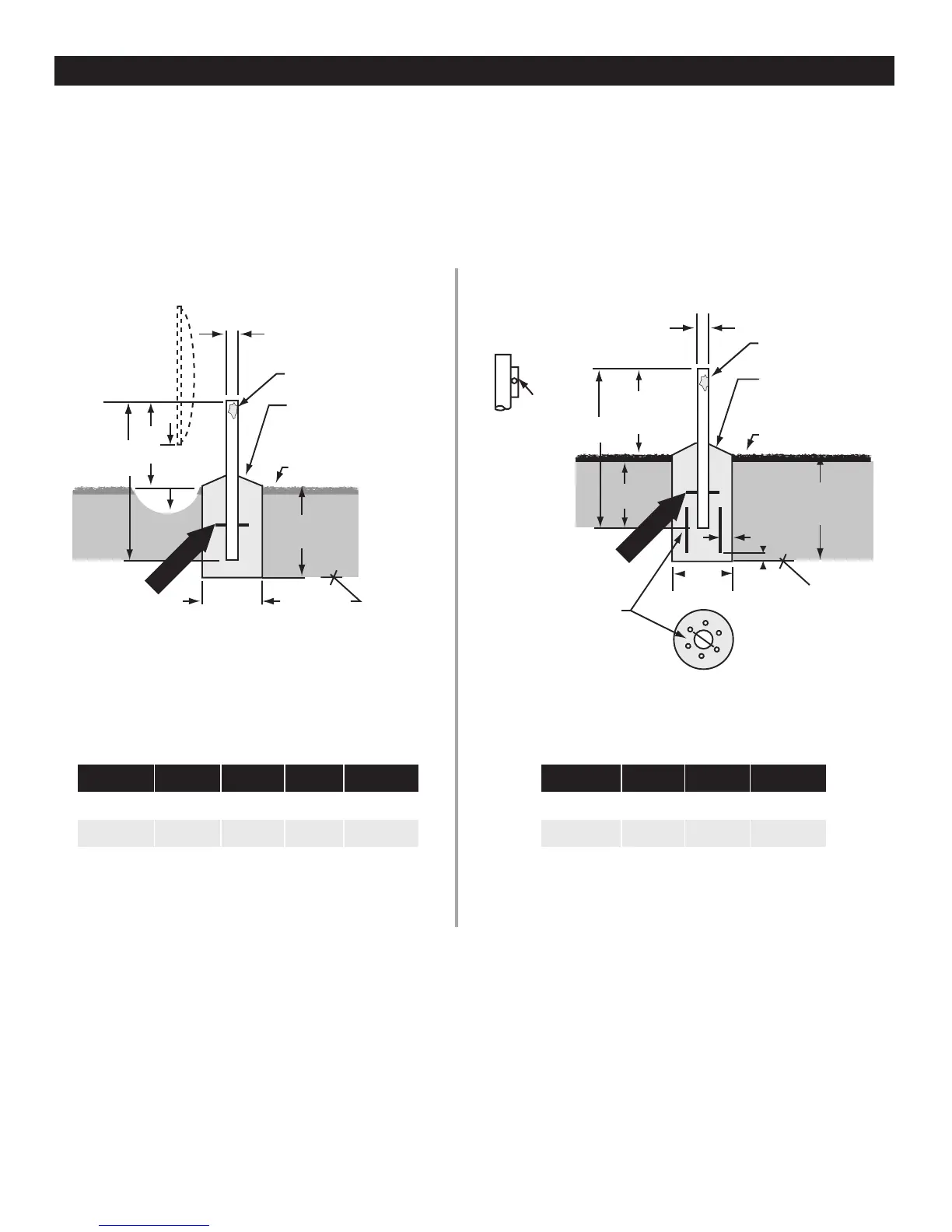
POLE SPECIFICATIONS
Ground Pole - 4.50 O.D. SCH 40 (4.026 I.D.) Steel - (Metric = 114.3 O.D. x 102.3 I.D. mm)
NOTE:
1. Poles are not supplied (purchased locally to ASTM A501) and must be field drilled 5/8” Dia (15.9mm) for M10 #3 rebar, drilled
.218 (5.55mm) for 1/4 - 20 self tapping grounding screw and galvanized or painted for protection.
2. Pole and foundation design based on the following criteria:
a. Uniform building code Exposure C and 1.5 stability factory.
b. Vertical soil pressure of 2000 pounds per square foot. (9765 Kilograms/meter square).
c. Lateral soil pressure of 300 pounds per square foot. (145 Kilograms/meter square).
d. Concrete compressive strength of 2500 pounds per square inch (176 Kg/Cm2) in 28 days.
CAUTION: The foundation design shown does not represent an appropriate design for any specific locality, since soil conditions vary and
may not meet design criteria given in Note 2. You should consult a local professional engineer to determine you soil conditions and
Appropriate foundation.
GROUND POLE INSTALLATION
114 mm
(4.5 in O.D.)
L
#3 rebar x 10 in
(9.5 rebar x 254 mm)
Insert through hole in
tube and center.
#3 Rebar
C
Minimum
Diameter
25 mm
to 51 mm
(1” to 2”) slope
for water run-off
Grade
Below
Frost Line
25 mm to 51 mm (1” to 2”)
slope for water run-off
Grade
114 mm
(4.5 in O.D.)
C
Minimum
Diameter
Below
Frost Line
Approx.
51 mm
(2 in)
1676 mm
(66 in) (See Note)
#3 rebar x .46 m (18”)
(9.5 rebar x 457 mm)
Insert through
hole in tube and center.
#3 Rebar
(6)#3 rebar x .6 m (24 in)
(9.5 x 610 mm)
at 60˚ apart (See note)
51 mm
(2 in)
Bubble
Level
Ground Pole Must Be
Vertical in All Directions
at Top
NOTE:
127 cm (50”) may
be increased to frost
line. Concrete and
length of rebar will
increase
accordingly.
Bottom View
Pier Foundations Deep Frost Line Foundations
Reflector Size: 1.8 m
Concrete Dimension
L A B C E
2438 mm 1270 mm 1359 mm 914 mm 424 mm
(
96 in) (50 in) (53 in) (36 in) 16.7 in
Concrete Volume: .84 m
3
(1.1 yd
3)
*NOTE: Clearance increases at elevations greater than 23˚
A
B
*E (See Note)
Fill Completely
with Concrete
Reflector Size: 1.8 m
Concrete Dimension
L A D C
2438 mm 1359 mm 1092 mm 737 mm
(
96 in) (53 in) (43 in) (29 in)
Concrete Volume: .72 m
3
(.94 yd
3)
*NOTE: 1676 mm (66 in) may be increased, concrete
and length of rebar will increase accordingly.
L
A
D
Fill Completely
with Concrete
Soil conditions vary and you should consult with a local professional engineer for modifications, if any, to suit local soil
conditions and code requirements.
Designs based on allowable vertical soil bearing pressure of 2000 psf and 125 mph wind velocity. Minimum compressive
Strength of concrete shall be 2500 psi at 28 days.
DESIGNS SHOWN BELOW DO NOT REPRESENT AN APPROPRIATE FOUNDATION FOR ANY
SPECIFIC LOCALITY OR ANTENNA INSTALLATION. THEY ARE PROVIDED FOR
REFERENCE PURPOSES ONLY.
 Loading...