ASSEMBLY ALIGNMENT PROCEDURE
7
Alignment with the satellite is obtained by setting polarization,
elevation, and azimuth. Charts 1, 2 and 3 are to determine the
values for your earth station antenna site. “∆L” is the difference
between the earth station antenna site longitude and the satellite
longitude. Use “∆L” and your earth station latitude to obtain
polarization, elevation or azimuth setting.
Elevation Alignment
Refer to Chart 1 to determine your elevation setting.
IMPORTANT: Before adjustment, loosen the two
bolts (13) (18) on each side of this housing (1/2
turn). Re-tighten all four bolts after adjustment is
completed.
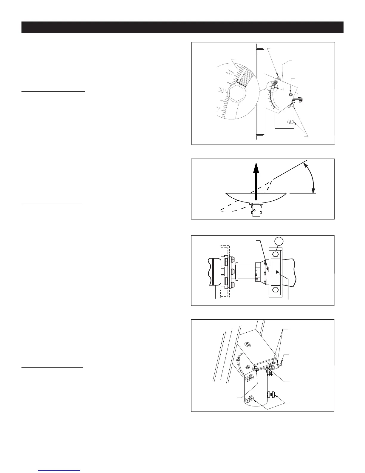
Turn elevation adjustment bolt, Item 9, clock-wise, to decrease
elevation, and counterclockwise to increase elevation. Align the
edge of bracket with the appropriate mark at the desired eleva-
tion reading (See Figure 2.0).This will be an approximate setting.
Optimum setting will be achieved when Fine Tuning. Refer to
Figure 2.3.
NOTE: When the reflector face is vertical,while
the beam elevation (beam) axis is 22.62°,the
offset angleof the antenna.(See Appendix,Outline
Drawing,Page 14).
Azimuth Alignment
Use Chart 3 and determine your azimuth setting. Values in
chart must be adjusted for magnetic deviation for
your location for correct compass reading. Equally
tighten the four azimuth locking bolts (15) until snug, and back off
1/8 turn. This will allow azimuth rotation with slight resistance,
without AZ/EL cap tilting on pole. Rotate the reflector and AZ/EL
cap, pointing it to the correct compass reading for your location
and satellite. Refer to Figure 2.1. If desired signal is not found,
increase or decrease elevation setting and repeat the azimuth
sweep until desired signal is found. Tighten progressively (1/8
turn each) all four azimuth bolts (15).Repeat until 70-80 ft-lbs (95-
108 N-m) torque is reached.
Fine Tuning
Snug tighten hex bolt/nut in curved slots (13) and pivot bolts (18)
(refer to Figure 2.0). Use a signal strength measuring device for
final adjustments to obtain maximum antenna performance. Alter-
nate between elevation and azimuth fine tuning to reach maxi-
mum signal strength, until no improvement can be detected. Top
plate locking bolts (18), 4 places, should be torqued to 6-8 ft-lbs
(8-11 N-m). See Figure 2.3. Turn the azimuth adjusting nuts (3)
clockwise or counter clockwise for azimuth fine tuning. Tighten
and torque all hardware(refer to Torque Chart on Page 2).
Polarization of Feed
Loosen two feed horn clamp bolts (26) and turn feed clockwise
or counterclockwise, depending on being east or west of the sat-
ellite as shown on Chart 3. Align marks on the horn clamp and
appropriate mark on the horn scale. Polarization chart assumes
antenna system polarization is Tx vertical and satellite vertical Pol
is perpendicular to plane of geostationary arc. For horizontal Tx
of antenna, feed must be rotated 90° from values shown. Start-
ing point for polarization adjustment is 0°, as shown in figure
2.0. Tighten and torque clamp bolts to 4 ft-lbs (5.4 N-m), after
setting.
ANTENNA ALIGNMENT PROCEDURE
Alignment with the satellite is obtained by setting polarization, ele-
vation and azimuth. Charts 1, 2 and 3 are to determine the values
for your earth station antenna site. “∆L” is the difference between the
earth station antenna site longitude and the satellite longitude. Use
“∆L” and your earth station latitude to obtain polarization, elevation
or azimuth setting.
Elevation Alignment
Refer to Chart 1 to determine your elevation setting. IMPORTANT:
Before adjustment, loosen the two bolts (13) (18) on each side
of this housing (1/2 turn). Re-tighten all four bolts after adjust-
ment is completed. Turn elevation adjustment bolt, Item 9, clock-
wise, to decrease ele
vation, and counterclockwise to increase ele-
vation. Align the edge of bracket with the appropriate mark at the
desired elevation reading (See FIgure 2.0). This will be an approxi-
mate setting. Optimum setting will be achieved when Fine Tuning.
Refer to Figure 2.3. NOTE: When the reflector face is vertical,
while the beam ele
vation (beam) axis is 22.62˚, the offset angle
of the antenna. (See Appendix, Outline Drawing, Page 14).
Azimuth Alignment
Use Chart 3 and determine your azimuth setting. Values in chart
must be adjusted for magnetic deviation for your location for
correct compass reading. Equally tighten the four azimuth locking
bolts (15) until sn
ug, and back off 1/8 turn. This will allow azimuth
rotation with slight resistance, without AZ/EL cap tilting on pole.
Rotate the reflector and AZ/EL cap, pointing it to the correct com-
pass reading for your location and satellite. Refer to Figure 2.1. If
desired signal is not found, increase or decrease elevation setting
and repeat the azimuth sweep until desired signal is found. Tighten
progressively (1/8 turn each) all four azimuth bolts (15). Repeat until
70-80 ft-lbs (95-108 N-m) torque is reached.
Fine Tuning
Snug tighten hex bolt/nut in curved slots (13) and pivot bolts (18)
(refer to Figure 2.0). Use a signal strength measuring device for final
adjustments to obtain maximum antenna performance. Alternate
between elevation and azimuth fine tuning to reach maximum signal
strength, until no improvement can be detected. Top plate locking
bolts (18), 4 places, should be torqued to 6-8 ft-lbs (8-11 N-m). See
Figure 2.3. Turn the azimuth adjusting nuts (3) clockwise or coun-
terclockwise for azimuth fine tuning.Tighten and torque all hardware
(refer to Torque Chart on Page 2).
Polarization of Feed
Loosen two feed horn clamp bolts (26) and turn feed clockwise or
counterclockwise, depending on being east or west of the satellite
as shown on Chart 3. Align marks on the horn clamp and appropri-
ate mark on the horn scale. Polarization chart assumes antenna
system polarization is Tx vertical and satellite vertical Pol is per-
pendicular to plane of geostationary arc. For horizontal Tx of anten-
na, feed must be rotated 90˚ from values shown. Starting point for
polarization adjustment is 0˚, as shown in figure 2.0. Tighten and
torque clamp bolts to 4 ft-lbs (5.4 N-m), after setting.
ALIGN THIS EDGE
WITH SCALE FOR
ELEVATION
READING
ELEVATION ADJUSTING
BOLT (9)
ELEVATION
LOCKING
BOLT (13)
ELEVATION
PIVOT
BOLT (18)
AZIMUTH LOCKING
BOLTS (15)
EXAMPLE SHOWN
AT 22.6 DEGREES
-40
+40
0
26
ALIGNMENT
MARK
ARROW
FIG. 2.0 - SETTING ANTENNA ELEVATION
FIG. 2.1 - ROTATING ANTENNA FOR AZIMUTH
FIG. 2.2 - POLARIZATION OF FEED
AZIMUTH
ADJUSTING
NUTS (3)
AZIMUTH
ADJUSTING
SCREW (24)
ADJUSTING
SCREW (21)
PIVOT BOLT
AZIMUTH
LOCKING
BOLTS (15)
TOP PLATE
LOCKING
BOLTS (18)
FIG. 2.3 - AZ/EL CAP MOUNT w/AZ
FINE TUNE
 Loading...