5
ASSEMBLY AND INSTALLATION
NOTE: 10mm tools fit M6 hardware. Recommendations for Site Selection, Assembly Tools Required for Assembly,
a Pre-Installation Checklist and a Hardware Sorter are provided in this manual for your convenience.
The AZ/EL cap can be installed on a ground pole or roof mount support. Mount should be assembled and in place, or
ground pole set, before installing the AZ/EL cap.
NOTE: For ground pole installations, allow concrete to cure before proceeding with installation.
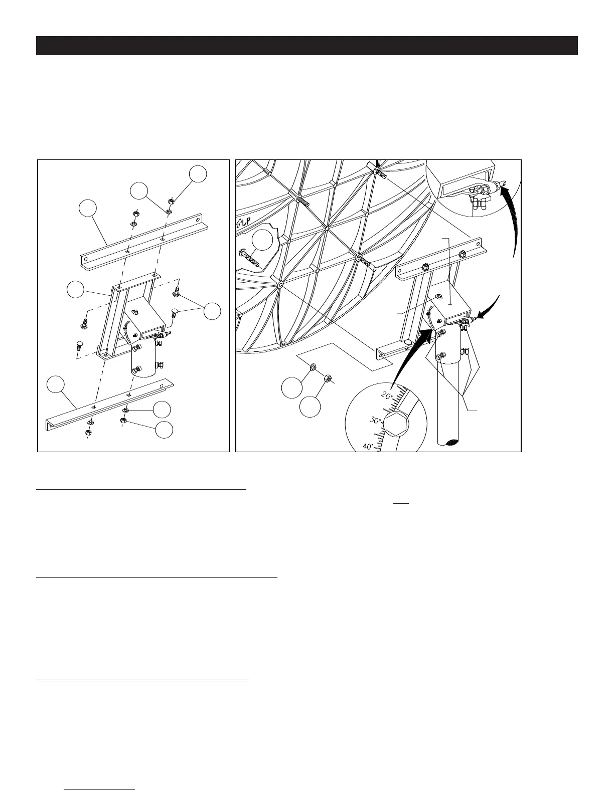
FIGURE 1.0 FIGURE 1.1
M12 LOCK WASHER
4 PLACES
M12
HEX NUT
4 PLACES
TOP/BOTTOM
ANGLE
2 PLACES
RD HD
SQ NK
BOLT
M12 x 25mm
4 PLACES
AZ/EL
Cap
ELEVATION
ADJUSTMENT
BOLT
AZIMUTH
LOCKING
BOLTS
AZIMUTH
FINE TUNING
ADJUSTMENT
BOLT
6
3
2
17
7A
6
2
3
1
2
3
ASSEMBLY AND INSTALLATION
AZ/EL FRAME ASSEMBLY (FIGURE 1.0)
Assemble top/bottom angles (6), to housing frame (7A)
with M12 x 25mm round head square neck bolts (17),
lock washers (2), and hex nut (3), as shown in Figure 1.0.
M12 hex nuts (3), must be finger tight.
INSTALLING AZ/EL CAP ON GROUND POLE
Back out (do not remove) the four azimuth locking bolts
from AZ/EL cap. Install cap onto top of ground pole or
base tube. To hold the AZ/EL cap in place while installing
antenna, temporarily tighten one of the azimuth locking
bolts.
INSTALLING ANTENNA TO AZ/EL CAP
Insert M12 x 100mm round head bolts (1) into antenna
mounting holes, as shown in Figure 1.1. Lift antenna and
align mounting bolts with holes in AZ/EL cap. Secure with
M12 lock washers (2) and hex nuts (3). Torque to 20 ft-lbs
(27 N-m).
IMPORTANT: For correct orientation of antenna, the
“UP” arrow must be as shown in Figure 1.1 and
Figure 1.2.
After M12 x 100mm antenna bolts are torqued, then
torque top/bottom angle bolts (17) and hex nuts (3) to 38
ft-lbs (51 N-m).
5
NOTE: 10mm tools fit M6 hardware. Recommendations for Site Selection, Assembly Tools Required for Assembly, a
Pre-Installation Checklist and a Hardware Sorter are provided in this manual for your convenience.
The AZ/EL cap can be installed on a ground pole or roof mount support. Mount should be assembled and in place, or
ground pole set, before installing the AZ/EL cap.
NOTE: For ground pole installations, allow concrete to cure before proceeding with installation.
AZ/EL FRAME ASSEMBLY (FIGURE 1.0)
Assemble top/bottom angles (6), to housing frame (7A)
with M12 x 25mm round head square neck bolts (17),
lock washers (2), and hex nut (3), as shown in Figure
1.0. M12 hex nuts (3), must be finger tight.
INSTALLING AZ/EL CAP ON GROUND POLE
Back out (do not remove) the four azimuth locking bolts
from AZ/EL cap. Install cap onto top of ground pole or
base tube. To hold the AZ/EL cap in place while install-
ing antenna, temporarily tighten one of the azimuth
locking bolts.
INSTALLING REFLECTOR TO AZ/EL CAP
Insert M12 x 100mm round head bolts (1) into Reflector
mounting holes, as shown in Figure 1.1. Lift Reflector and
align mounting bolts with holes in AZ/EL cap. Secure
with M12 lock washers (2) and hex nuts (3).Torque to 20
ft-lbs(27 N-m).
IMPORTANT: For correct orientation of
Reflector, the“UP”arrow must be as shown in
Figure 1.1 and Figure 1.2.
After M12 x 100mm Reflector bolts are torqued, then
torque top/bottom angle bolts (17) and hex nuts (3) to
38ft-lbs (51 N-m).
 Loading...