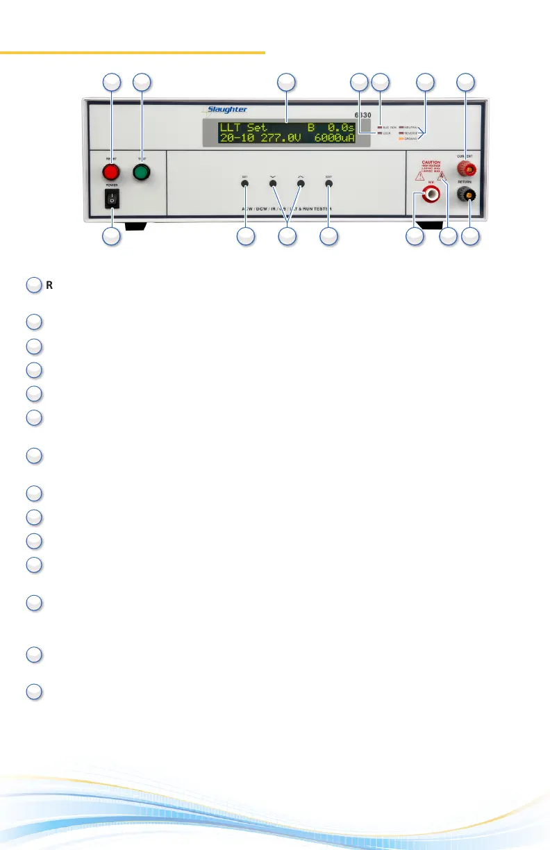
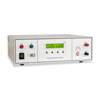
Front Panel Controls
1.
RESET BUTTON: Red momentary contact switch used to reset the instrument in case of a
failure. Also serves as an abort signal to stop any test in progress.
TEST BUTTON: Starts a test.
LCD DISPLAY: 20 x 2 character display.
LOCK INDICATOR: This LED indicates that the lock feature has been enabled.
BUS INTERFACE INDICATOR: This LED indicates that the bus interface has been enabled.
FAULT CONDITION INDICATORS: These LED’s indicate that the Neutral, Reverse, and
Ground line condions have been acvated during a Line Leakage test.
CURRENT OUTPUT TERMINAL: Used to aach the current test lead or test xture to the
instrument. Provides the high current output from the instrument.
POWER SWITCH: Rocker-style switch with internaonal ON ( | ) and OFF (0) markings.
SET KEY: Use this key to advance forward through the setup menus.
UP-DOWN ARROW KEYS: Use these keys to cycle through test parameter setup.
EXIT KEY: Use this key to exit any menu or to clear an unwanted entry in a
parameter eld.
HIGH VOLTAGE OUTPUT TERMINAL: Provides the high voltage used during a Hipot test.
Connector used to aach the high voltage test lead, adapter box high voltage lead or test
xture high voltage lead to the instrument.
HIGH VOLTAGE INDICATOR: This indicator ashes to warn the operator that high voltage
is present at the high voltage output terminal.
RETURN OUTPUT TERMINAL: Provides the return current path. Connector used to aach
the return test lead, adapter box return lead or test xture return lead to the instrument.
(6330 Front Panel)
10
10
11
11
12
12
13
13
14
14
2
2
3
3
4
4
5
5
6
6
7
7
8
8
9
9
1
1