Back Panel Controls
2.
(6330 Back Panel)
10
11
12
13
14
15
2
3
4
5
6
7
8
9
1
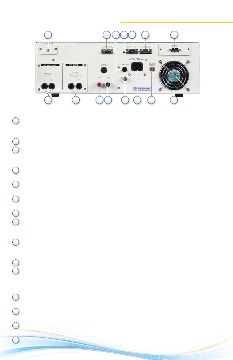
EXTERNAL MEASURING DEVICE: Provides an access port for a custom measuring device. The
port may be acvated during Line Leakage tesng from the instrument’s menu system. The
operator must supply the appropriate measuring device as none is provided.
POWER CONTROL: N/A
FUSE RECEPTACLE: Fuse rang is 6.3 A at 250 VAC. To change the fuse, unplug the power (mains)
cord and turn the fuse receptacle counterclockwise. The fuse compartment will be exposed.
Please replace the fuse with one of the proper rang.
CALIBRATION BUTTON: To put the instrument into the calibraon mode push this buon and
turn on the power switch simultaneously.
SIGNAL INPUT: 9-pin D-type subminiature male connector for remote control of TEST, RESET,
AND INTERLOCK funcons as well as remote memory tests recall.
SIGNAL OUTPUT: 9-pin D-type subminiature female connector for monitoring PASS, FAIL, and
PROCESSING output relay signals.
BUS INTERFACE: Oponal connector for interconnecon to RS-232 bus interface.
DUT POWER INPUT: Provides the line and neutral connecons for an input power source to be
used during Funconal Run and Line Leakage tesng. Only a U.S. style single phase unbalanced
power source may be used.
DUT POWER OUTPUT: Provides the line and neutral connecons from the 6330 to the DUT during
Funconal Run and Line Leakage tesng. Provides the high voltage connecons to the DUT during
ACW, DCW and IR tesng if the DUT OUTPUT and DUT-HV parameters are turned ON.
GROUND CONNECTION: Connector used to aach the adapter box ground lead to the instrument.
CASE CONNECTION: Provides the return connecon during ACW, DCW or IR tesng. This
terminal is wired in parallel with the return terminal during a Ground Bond test and may be
used in place of the front panel connecon. During a Line Leakage test this connecon provides
a connecon to one side of the measuring device (MD).
CHASSIS GROUND (EARTH) TERMINAL: This safety terminal should be connected to a good
earth ground before operaon.
INPUT POWER RECEPTACLE: Standard IEC 320 connector for connecon to a standard NEMA
style line power (mains) cord.
VOLTAGE SELECT SWITCH: Sets the line voltage conguraon of the instrument. In the le
posion it is set for 115 volt operaon, in the right posion it is set for 230 volt operaon.
THERMAL FAN: Runs connuously to cool the instrument.
2 3 4 5 6 71
10 11 12 13 14 158 9


 To Next Page