Repair Parts and Maintenance Guide
54
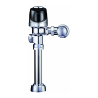
Sensor Flushometers
The information contained in this document is subject to change without notice.
Optima
®
Flushometers
Repair Parts and Maintenance Guide
54
Sensor Flushometers
ATTENTION INSTALLERS: With the exception of the control stop inlet,
DO NOT USE pipe sealant or plumbing grease on any valve component or
coupling! To protect the chrome or special nish of Sloan ushometers,
DO NOT USE toothed tools to install or service these valves. Use our A-50
Super-Wrench
™
or other smooth-jawed wrench to secure couplings.
Regulations for low consumption xtures (1.6 gpf/6.0 Lpf closets and
1.0 gpf/3.8 Lpf urinals) prohibit use of higher ush volumes.
Urinals (EL-1500 Sensor)
When the sensor detects a user, a slow ashing red light appears in the
sensor window. After eight (8) to ten (10) seconds, the light ashes rapidly
to indicate that the sensor is armed. When the sensor no longer detects a
user, the sensor immediately activates the solenoid valve after a 0.5 second
delay.
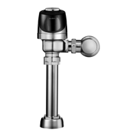
Water Closets (EL-1500-L Sensor)
Detection and activation are the same as for the urinal EL-1500 sensor
(ABOVE) except when the sensor no longer detects an user, the sensor
activates the solenoid valve after a three (3) second delay.
The EL-1500 urinal and EL-1500-L closet self-adaptive sensors are
equipped with a “Sentinel Flush” feature. These units automatically activate
the solenoid every twenty-four (24) hours after the last user.
1. Valve does not function (red light does not flash when user
steps in front of sensor).
A. No power is being supplied to sensor. Ensure that the main power is
turned “ON”. Check transformer, leads and connections. Repair or
replace as necessary.
B. EL-1500/EL-1500-L sensor is not operating. Replace sensor.
2. Valve does not function (red light flashes when user steps in
front of sensor).
INDICATOR: The red light stops flashing when user steps away
and the valve makes a “clicking” sound but does not flush.
A. No water is being supplied to the valve. Make certain that water
supply is turned “ON” and the control stop is open.
B. EL-128-A cartridge is fouled or jammed. Turn electronic power to
valve “OFF” (failure to do so could result in damage to the solenoid
coil). Remove the solenoid operator from the valve and remove the
EL-128-A cartridge. Clean and/or repair as necessary.
INDICATOR: The red light stops flashing when user steps
away but the valve does NOT make a “clicking” sound and
does NOT flush.
A. EL-163-A solenoid shaft assembly is fouled or jammed. Turn
electronic power to valve “OFF” (failure to do so could result in
damage to the solenoid coil). Remove EL-101 or EL-166 nut from the
solenoid operator. Remove the coil from the solenoid operator. Use
a spanner wrench or pliers to remove the EL-163-A solenoid shaft
assembly from valve. Clean and/or replace as necessary. Be sure to
replace plunger spring when reassembling solenoid shaft assembly.
INDICATOR: The red light flashes three (3) fast flashes, three (3)
slow flashes then three (3) fast flashes (“S-O-S”) and continues
to repeat this cycle even when user steps out of the sensor’s
detection range.
A. EL-1500/EL-1500-L sensor wiring connections are incorrect. Rewire
sensor to valve. One solenoid lead connects to the “TO VALVE”
connection on sensor. One transformer lead connects to the “24
VAC IN” connection on sensor. Second solenoid lead and second
transformer lead connect together.
B. Wiring to sensor is ground shorted. Find short in wiring circuit and
correct.
C. EL-165-2 solenoid coil is burnt out or coil is not connected to
solenoid plunger shaft. Reinstall or replace coil as necessary.
3. Range too short.
A. Power down unit for 30 seconds. Power up. Wait six minutes for
calibration.
B. If reset does not work, replace.
4. Volume of water is insufficient to adequately siphon fixture.
A. Control stop is not open wide enough. Adjust control stop for desired
water delivery.
B. Low consumption unit is installed on water saver or conventional
xture. Replace diaphragm component parts of valve with kit that
corresponds to appropriate ush volume of xture.
C. Inadequate water volume or pressure available from supply. Increase
pressure or supply (ow rate) to the valve. Consult factory for
assistance.
5. Length of flush is too long (long flushing) or valve fails
to shut off.
A. Water saver valve is installed on low consumption xture. Replace
diaphragm component parts of valve with kit that corresponds to
appropriate ush volume of xture.
B. Relief valve in diaphragm is not seated properly or by-pass hole in
diaphragm is clogged. Disassemble inside diaphragm component
parts and wash parts thoroughly. Replace worn parts if necessary.
6. Water splashes from fixture.
A. Supply ow rate is more than necessary. Adjust control stop to meet
ow rate required for proper cleansing of the xture.
B. Closet valve is installed on urinal xture. Replace closet diaphragm
component parts with proper urinal kit (inside diaphragm assembly or
inside parts kit).
CARE AND CLEANING INSTRUCTIONS
DO NOT USE abrasive or chemical cleaners to clean ushometers or sensor
that may dull the luster and attack the chrome or special decorative nishes.
Use ONLY mild soap and water, then wipe dry with a clean towel or cloth.
When cleaning the bathroom tile, protect the ushometer from any
splattering of cleaner. Acids and cleaning uids can discolor or remove
chrome plating.
When assistance is required, please contact
Sloan Technical Support at: 1-888-SLOAN-14 (1-888-756-2614).
TROUBLESHOOTING GUIDE
 Loading...