VHX-7000-H Controller User Manual V1.0 Page 3 / 24 © 2023 Smart-e (UK) Ltd
Press and hold this button (about 10 seconds) until Status
LED starts flashing, Controller will be reset automatically.
The red LED will light on when the Controller is powered
on.
The status LED will flash in yellowish-green every 1
second until Controller boots up completely and Control
LAN is ready, then it becomes solid.
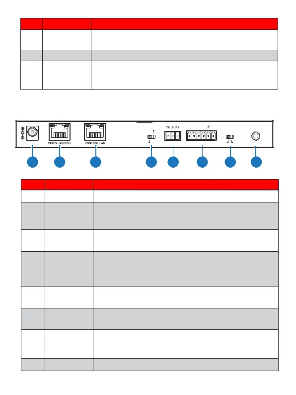
5.2 Rear Panel
MCU
IO LEVE L
IR IN
DC 12V
NORMAL
5V 12V
1 2 3 4 5 6 7 8
DC 12V/1A power input port.
100M Video LAN port, supporting POE function.
Note: When POE is enabled, DC 12V/1A power supply is
not required.
The TCP/IP control network port.
Normal mode (Default): The RS-232 port is used for
serial port commands control.
MCU mode: The RS-232 port is used for MCU
software upgrade.
RS-232 serial communication port.
4 channel I/O level outputs, 1 channel grounding,
1 channel power supply to the outside.
Used to control I/O level output and VOUT
voltage. Switch to left: 5V I/O level output, VOUT
is 5V. Switch to right: 12V I/O level output, VOUT is
12V.
12V IR signal input port.