F
E
D
-7-
Installation
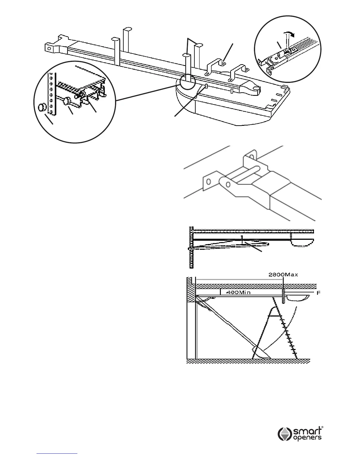
2.1) Insert shuttle into track by locating the cut out in
the bottom of the track at the powerhead end of the
track. It is important that the allen key bolt where
the arm connects onto the shuttle is facing the door.
Do not install it the wrong way round.
2.2) Move shuttle to half way along the rail section, grease
the chain and sprocket with a lithium type grease or
equivalent. Do not use oil based lubricants.
2.3) Place track onto powerhead so that the track
slides into spline shaft. Position the brackets (E)
on the studs and secure in place using ni-lock nuts
supplied. Lock the brackets to the rail by tightening
the ni-lock nuts. Do not over tighten the nuts.
2.4) Remove excess chain slack by tightening the chain
tightening screw (C) in (Fig. 4b) in a clockwise
direction (when viewed from the power head end of
the rail). Do not over tighten the chain, just enough
to remove the slack.
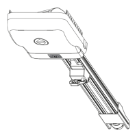
2.5) Fix the Smart Lifter opener to the lintel or to the
ceiling with the correct xing (Fig. 5), maintaining
a minimum gap of 30mm from the top panel’s
maximum height (Fig. 6). Check measurements
before drilling.
2.6) Insert the bolts supplied into the cutouts on both
sides of track at powerhead end. Slide bolts on
track to the correct hanging location to pick up
noggins or xing points. Place non ni-lock nuts onto
the bolt (ref Fig. 4c) and tighten. Place bracket (F)
onto bolt so that it sits against the nut and secure
with ni-lock nut supplied - do not over tighten.
Smart Openers recommend the tting of all four
straps on every installation.
2.7) Fix the Smart Lifter opener to the ceiling with
appropriate fasteners (Fig.7). Cut off any xing
strap excess.
Warning: Make sure the opener is afxed to noggins
in ceiling and not just to plasterboard. Failure to have
a safe and secure xing will lead to opener falling
causing serious personal and /or property damage.
Note: A set of xing straps should be located in the
centre of the aluminium rail to prevent rail ex that will
result in phantom reversing.
Fig. 4a
Fig. 5
Fig. 6
Fig. 7
C
Fig. 4b
30mm min.
2.8) Assemble straight arm and hockey stick using bolts
and nuts provided. Connect arms to door bracket
with pin and retainer clip and arms to shuttle on
opener with allen head bolt provided in shuttle.
Fig. 4c
NON
NI-LOCK
NUT
BOLT
NI-
LOCK
NUT