EasyManuals Logo

Smartrise HPV900 Manual

Default Icon
32 pages
To Next Page IconTo Next Page
To Previous Page IconTo Previous Page
Page #10 background imageLoading...
Page #10 background image
Load Weighing Device
Page 2 ©2021 Smartrise Engineering, Inc. All Rights Reserved September 29,2021
Figure 2: Sensor
Installation
Move the car to the lowest level prior to installing the load cells. After the car is at the lowest
level, install the crosshead sensors according to manufacturer recommendations on top of the
crosshead beam.
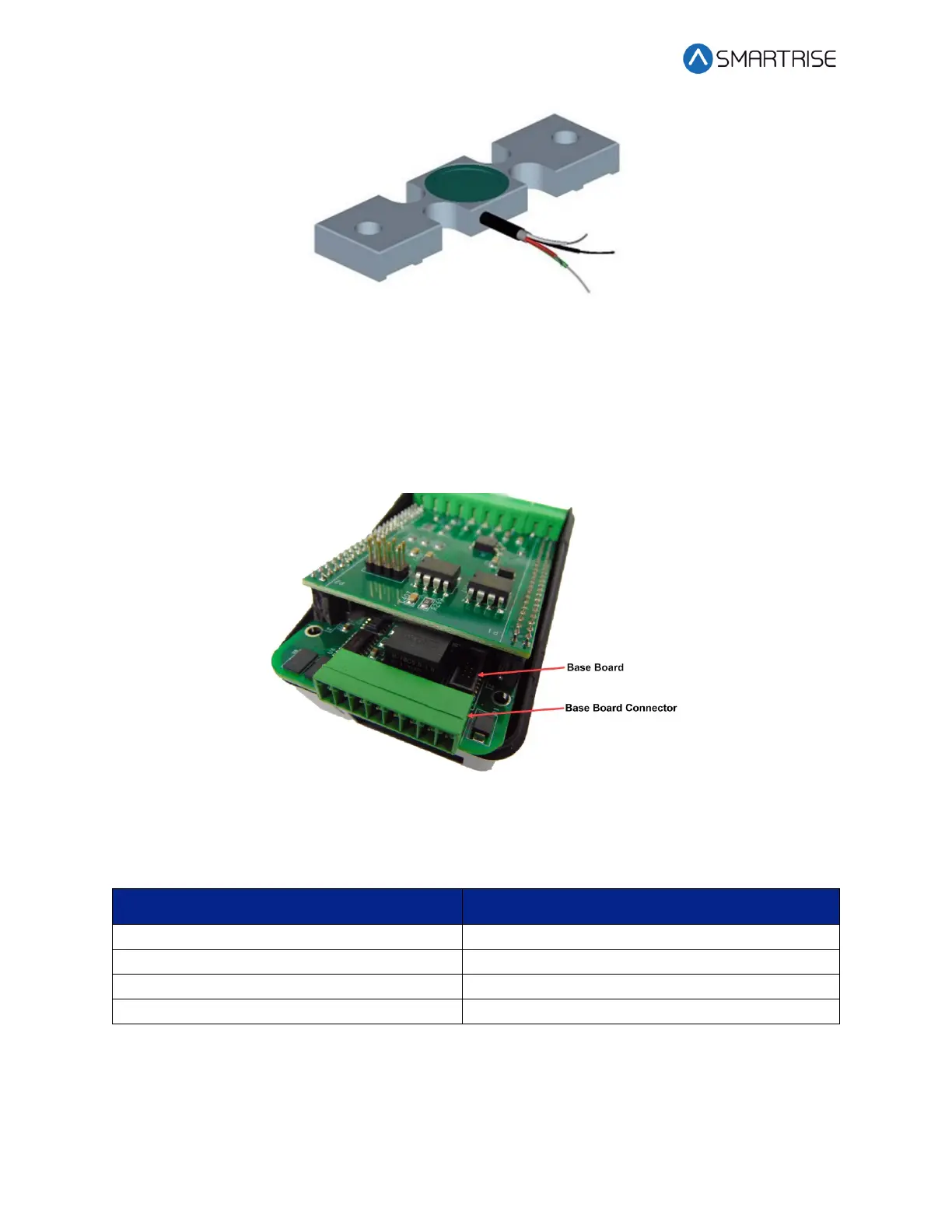
Figure 3: Base Board Connector
The table below lists the wiring configuration of the Sensor to the Base board of the LWD.
Table 1: Wiring Configuration of the Sensor to the Base Board of the LWD
Sensor
LWD Base Board Connector
Green
Pin 5
White
Pin 6
Black
Pin 7
Red
Pin 8

Table of Contents

Other manuals for Smartrise HPV900

Questions and Answers:

Question and Answer IconNeed help?

Do you have a question about the Smartrise HPV900 and is the answer not in the manual?

Smartrise HPV900 Specifications

General IconGeneral
BrandSmartrise
ModelHPV900
CategoryController
LanguageEnglish

Related product manuals