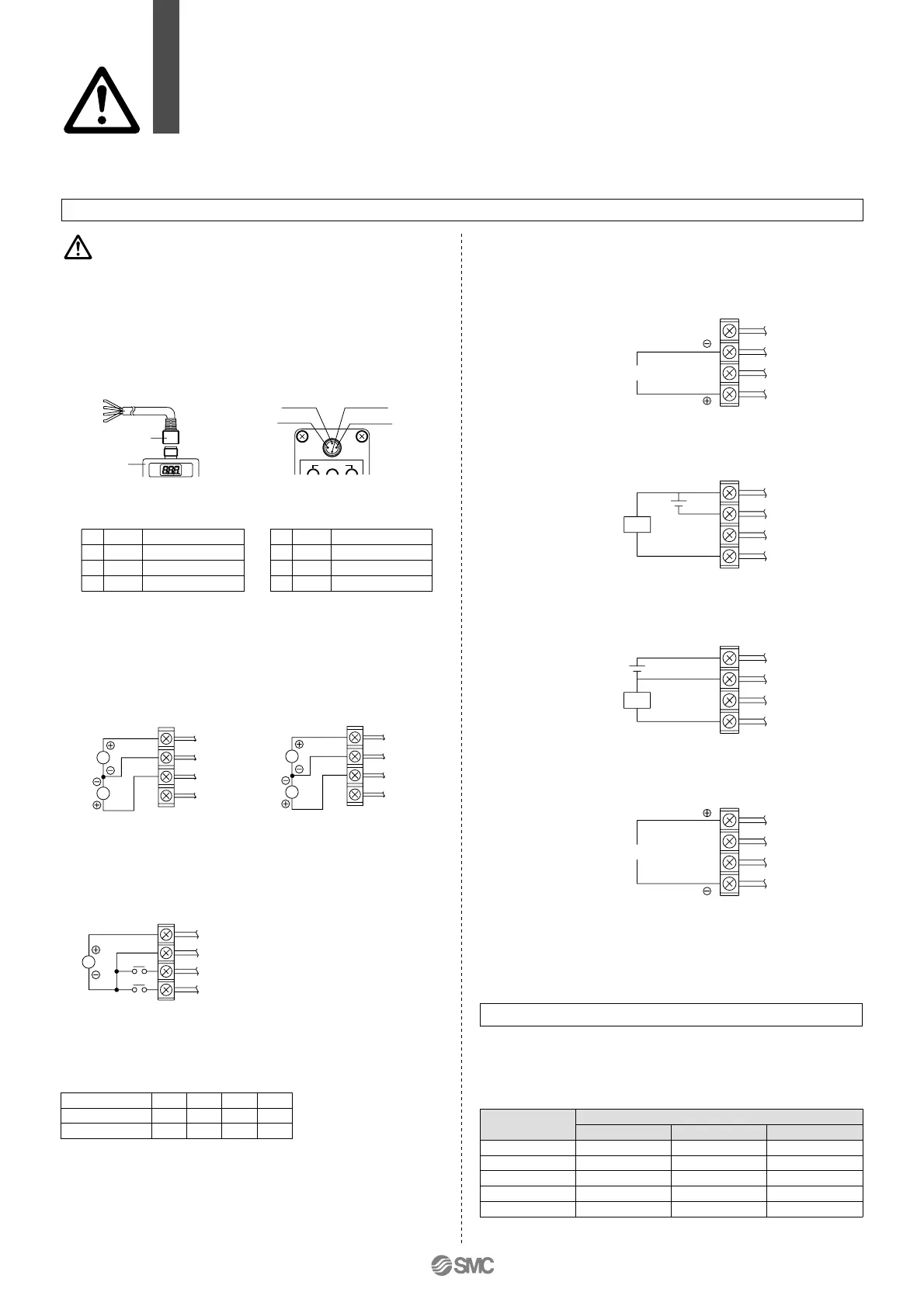
Wiring
Connect the cable to the connector on the body
with the wiring arranged as shown below.
Proceed carefully, as incorrect wiring can
cause damage.
Further, use DC power with sufficient capacity
and a low ripple.
Caution
Note) A right angle type cable is also available.
The entry direction for the right angle type connector is to the left (SUP
port side).
Never turn the connector as it is not designed to turn.
1
2
3
4
Brown
Blue
White
Black
Note)
Body
3: (Blue) 1: (Brown)
2: (White)
4: (Black)
Wiring diagram
Brown
Blue
White
Black
Current signal type
Analogue output, voltage type
Switch output, NPN type
Switch output, PNP type
Analogue output, current type (sink type)
Vs
Vs
A
Brown
Blue
White
Black
Voltage signal type
Brown
Blue
White
Black
Monitor output current
Brown
Blue
White
Black
Load
∗
Brown
Blue
White
Black
Load
∗
Vs
Vin
Vs: Power supply 24 VDC
12 to 15 VDC
A: Input signal 4 to 20 mADC
0 to 20 mADC
Vs: Power supply 24 VDC
12 to 15 VDC
Vs : Power supply 24 VDC
12 to 15 VDC
Vin: Input signal 0 to 5 VDC
0 to 10 VDC
RESET
Current signal type
Voltage signal type Preset input type
Preset input type
Regulating pressure range, by unit of standard measured pressure
Brown
White
Blue
Black
Power supply
Input signal
GND (COMMON)
Monitor output
S1
S2
Preset pressure
Unit
MPa
kgf/cm
2
bar
PSI
kPa
OFF
OFF
P1
ON
OFF
P2
OFF
ON
P3
ON
ON
P4
1
2
3
4
Brown
White
Blue
Black
Power supply
Input signal
GND (COMMON)
Monitor output
Blue
Brown
White
Black
S2
S1
Monitor output wiring diagram
∗ When 30 mA DC or more is applied, detecting device for overcurrent starts
activating and then emits an error signal.
(Error number “5”)
Brown
Blue
White
Black
Monitor output current
18
Series ITV1000/2000/3000
Specific Product Precautions 2
Be sure to read before handling.
Refer to pages 15 and 16 for safety instructions and precautions.
Set Pressure Range
The regulating pressure range, by unit of standard
measured pressure, is shown in the table below.
ITV
씲
01
씲
ITV
씲
03
씲
Regulating pressure range
ITV
씲
05
씲
0.005 to 0.1
0.05 to 1
0.05 to 1
0.7 to 15
5 to 100
0.005 to 0.5
0.05 to 5
0.05 to 5
0.7 to 70
5 to 500
0.005 to 0.9
0.05 to 9
0.05 to 9
0.7 to 130
5 to 900
One of the preset pressures P1 through P4 is selected by the ON/OFF
combination of S1 and S2.
∗ For safety reasons, it is recommended that one of the preset pressures be
set to 0 MPa.

 Loading...