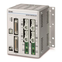
Do you have a question about the SMC Networks LECP6 Series and is the answer not in the manual?
Explains hazard levels (Caution, Warning, Danger) and their associated injury risks.
Covers product compatibility, personnel training, service safety, and conditions requiring special measures.
Summarizes key functions: actuator control, force operation, separated power supply, return to origin, alarm detection, step data, and modes.
Explains LED indicators, alarm handling, operation pattern setting, and trial run procedures.
Lists core specifications including motor compatibility, power, I/O, communication, memory, and environmental ratings.
Describes screw and DIN rail mounting, and the procedure for connecting the ground wire.
Illustrates wiring for CN1 (Power), CN2/CN3 (Motor/Encoder), and CN4 (Serial I/O) connectors.
Details plug specifications and wiring instructions for power supply, stop switch, and lock release.
Describes the function and connection of parallel I/O input terminals (COM, IN0-IN5, SETUP, HOLD, DRIVE, RESET, SVON).
Explains step data for operation patterns, provides an example, and includes a caution for data writing.
Explains the process of returning to origin to establish the home position before operations.
Describes the positioning operation where the actuator moves to a target position based on step data.
Explains the pushing operation, successful completion, failure scenarios, and work piece movement.
Demonstrates pushing operation with step data and a flow chart of the control sequence.
Details Step data ALM1, Parameter ALM, and Small Dec alarms, including causes and countermeasures.
Emphasizes safety during wiring, preventing shock, using specified cables, and taking noise mitigation measures.
Diagnoses and solutions for controller LED issues (OFF or ALM ON), covering power and alarm conditions.
Addresses communication issues with LEC-W2, focusing on USB drivers and COM port configuration.
Covers issues like actuator not moving, occasional movement, incorrect movement, and insufficient speed.
Addresses wiring faults, data writing errors, parameter issues, and voltage drops affecting actuator operation.
| Model | LECP6 Series |
|---|---|
| Category | Controller |
| Interface | Ethernet |
| Connectivity Technology | Wired |
| Ports | 6 |
| Operating Temperature | 0°C to 40°C |
| Storage Temperature | -20°C to 70°C (-4°F to 158°F) |


