- 30 -
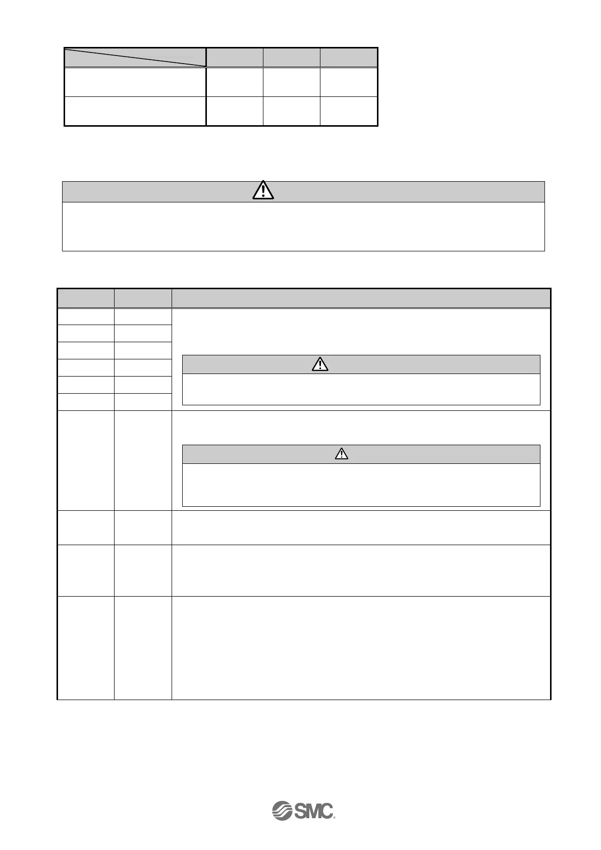
Effective condition of the Parallel I/O signal
DRIVE
(Operation start instruction)
(“-” = It doesn't depend in the ON/ OFF state of the each output signal)
*1) During the positioning operation the SETUP input will be disabled whilst hold is in operation.
SETUP and DRIVE can only be accepted during the above conditions. An Alarm condition will
happen during all other times. Keep the input signal combination for 15 ms (30 ms if possible) or
longer.
When the operation is started and DRIVE is turned OFF, a Bit no. corresponding to the
number of the active step data will be output from these terminals.
This output signal will be updated when DRIVE (A11) terminal is be turned ON.
When RESET is turned ON, these terminals are turned OFF.
During the alarm, these terminals output the alarm group.
This terminal is ON during the movement of the electric actuator.
(During the positioning operation, etc.).
During the pushing operation without movement (no movement but the electric
actuator generating the pushing force), BUSY is OFF. BUSY signal stays on for 50ms
or longer after operation starts.
When the electric actuator is within the range between Area 2 and Area1 in the step data,
this terminal will be turned ON. The range changes depending on the active step data.
When the electric actuator is in the SETON status (the position information is established),
this terminal is turned ON.
When the position status is not established, this terminal is OFF.
Because of the electric actuator action, if output INP is ON, the electric actuator condition
can vary.
At the origin when within the ± “default in position” in the Basic parameter.
During positioning operation
Turns ON when the current position is within "Step data position +/- positioning range".
During pushing operation.
When the pushing force exceeds the value set in the step data “Trigger LV”.

 Loading...


