- 14 -
(4) Power ON alarm (error)
Ensure the stop is not activated and then supply 24 VDC power.
If the LED [PWR] lights in green, the controller is in the normal condition.
However, if the LED [ALM] lights in red, the controller is in the alarm (error) condition.
In case of alarm (error) condition:
Connect a PC or the teaching box to the CN4 serial I/O connector and check the details of the alarm.
Then, remove the cause of the error referring to the
“12. Alarm Detection”
Please refer to the manuals of the controller setting software or the teaching box for details of the
alarms.
(5) Operation pattern setting
Set up the step data and parameters using the controller set up kit or the teaching box.
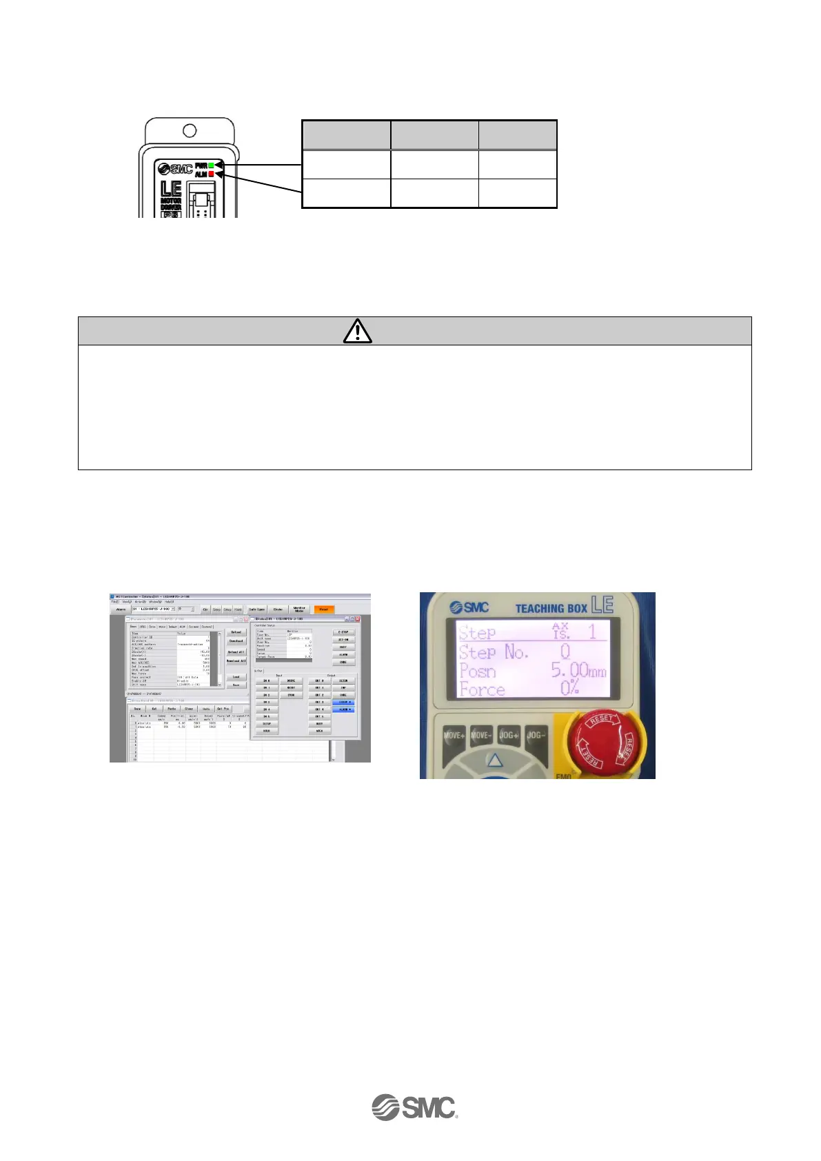
●Controller set up kit ●Teaching box
Please refer to the manuals of the controller setting software or the teaching box for how to setup the
operation pattern.
(6) Trial run
Please refer to the manuals of the controller setting kit or the teaching box manual for how to perform a
trial run.

 Loading...


