VBA-OM-L007-E
OPERATION MANUAL VBA-M3
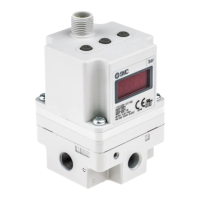
Booster regulator
VBA1 A / 2 A / 4 A Series
Contents
● Descriptions and specifications of the components
● Ope rati on Precau tions
● Before reques ting ser vice
Thank you for choosing this SMC product. This operation manual provides
essential information to ensure its optimum performance and lifespan.
Keep this manual accessible and refer to it if problems occur. Please refer
to the latest catalogue, drawings and maintenance procedures for product
configuration and specifications.
● Descriptions and specifications of the components
Specifications
Ambient and
operating fluid
temperature
Lubrication is not allowed
Governor*
(Pressure adjusting
mechanism)
*The default pressure of the handle is 0. When the air is supplied, the
pressure is relieved.
● Handling Precautions
To ensure safe and optimum operation, confirm the product’s
specifications before use. Operating the product out of the scope of its
specifications may cause failure or accident.
Operating Location
CAUTION
Do not install the product where it can be exposed to rain or direct
sunlight.
Do not install the product where it can be affected by vibration.
Installation
Since the booster regulator vibrates due to the reciprocation of the
internal piston, mount 4 bolts onto the mounting holes and tighten them
completely.
CAUTION
(1)Lifting
When transporting this product, hold it lengthwise with both hands.
Never hold it by the black handle that protrudes from the centre because
the handle could become detached from the body, causing the body to
fall and leading to injury.
(2)Installation
Mount the booster regulator so that the tie-rod/cover are placed
horizontally.
A malfunction will occur if it is vertical.
If vibration of the booster regulator may cause problems, take
countermeasures in your application to prevent vibration.
Ensure there is enough space for maintenance.
When connecting the booster regulator with the VBAT tank, be sure to
read the operation manual and use the accessories provided with the
tank.
Key
O: Can be used
X: Cannot be used
O O
X
Piping
Connect IN port with the air source, and OUT port with an actuator.
Install a silencer or exhaust cleaner at the exhaust port of the booster
regulator to reduce noise, if necessary.
Exhaust cleaner
model No.
* Separate piping should be prepared to
connect the booster regulator with the
exhaust cleaner.
* If the tank is not used, mount the booster
regulator away from the floor in accordance
with the installation distance stated above.
The elbow for silencer (option) can be used only for mounting a silencer
to the exhaust port. Do not use it for the IN port and the OUT port.
Prepare piping separately to exhaust remotely by connecting pipes to
the exhaust port.
O X X X
When preparing piping for the booster regulator, always fasten the
threads with correct tighten torque as shown in the below table.
When mounting the silencer and the elbow for silencer, hold the end of
the body (the side without thread) and screw it in. When the screw
becomes slightly tight, tighten it further for approximately 1/4 turn with a
spanner whose size is appropriate for the width across flat of the
hexagon head.
CAUTION
(1)Flushing ··· Care should be taken especially for the precision parts.
Before piping, flush pipes to remove cutting chips, cutting oil, and
dust which may cause malfunction or lower the durability of the
booster regulator. If they enter inside the booster regulator, they
could cause the booster regulator to malfunction or its durability
could be affected
(2)Piping size
Ensure that the piping size corresponds to the port size to achieve the
full function of the booster regulator. If the piping is too small, the
function will be reduced due to the pressure loss.
(3)Exhaust air
Individual piping is necessary for exhaust air of the booster regulator.
Using common piping for exhaust may cause malfunction due to back
pressure.
If inlet pressure and outlet pressure are set close together, air may leak
from the exhaust port. This is normal. This occurs when the booster
regulator is on standby for switching.
(4)Particle generation
There is a sliding part inside the booster regulator, and it generates
particles. Install an air filter or mist separator at the outlet if necessary.
The booster regulator contains lubrication (grease / turbine oil) in the
exhaust air.
Air Supply
CAUTION
(1)Quality of Air Source ··· Take care especially for precision parts.
Connect a mist separator at the inlet of the booster regulator. If the
quality of compressed air is not fully controlled, it may cause a
malfunction or deterioration of durability.
Although a wire mesh is installed at the IN port of the booster regulator
to prevent simple particles from entering, it cannot continuously filter
particles or separate drainage. Make sure to install a mist separator
(model AM Series) at the inlet of booster regulator.
If dry air (atmospheric pressure dew point –23°C or less) is used, the
life expectancy may be shortened because dry air will accelerate
evaporation of grease inside.
If necessary connect the lubricator only at the outlet. Accumulation of
oil in the booster regulator may cause malfunction.