Do you have a question about the SMC Networks JXC61 and is the answer not in the manual?
Outlines the main functions and capabilities of the Step Motor Controller.
Details the components and connections of the controller system.
Explains the part number construction for ordering the JXC51/JXC61 controller.
Details available options and compatible accessories for the controller.
Guides through the initial setup steps for the controller before operation.
Lists the fundamental technical specifications of the JXC51/JXC61 controller.
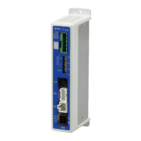
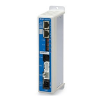
Details the functions and labels of each part of the controller unit.
Provides visual representations of the controller's physical dimensions.
Describes methods for mounting the controller and connecting grounding.
Details the wiring connections for the power connector.
Explains connections for motor power and encoder interfaces.
Details serial I/O connections for teaching box and PC.
Describes the connections and usage of the parallel I/O connector.
Lists the specifications for the supplied power supply plug.
Outlines the required specifications for electric wires to be used.
Guides on wiring the power supply plug, including stop and lock release.
Provides an example wiring circuit for a single controller with a teaching box.
Shows an example wiring circuit for multiple controllers using relay contacts.
Illustrates an example circuit for motor power shutdown using relay contacts.
Lists the input and output specifications for parallel I/O.
Explains the NPN and PNP types for parallel I/O configurations.
Provides a detailed breakdown of parallel I/O signals and their functions.
Shows practical examples of parallel I/O wiring configurations.
Explains how to set up step data for operation patterns.
Details the basic parameters that define controller and actuator operating conditions.
Configures settings for the return-to-origin operation.
Explains when and how to perform the return-to-origin operation.
Describes how to execute positioning operations using step data.
Details the process and outcomes of pushing operations.
Explains different methods for stopping actuator operation.
Provides an example of setting up and executing a positioning operation.
Demonstrates an example of setting up and performing a pushing operation.
Outlines the initial startup steps for battery-less absolute encoders.
Details the procedures for initial power-up and setup.
Explains the procedure for restoring or reapplying power.
Describes how to clear specific alarms by cycling power.
Guides through the power-on sequence and return-to-origin.
Details the steps and timing for positioning operations.
Details the steps and timing for pushing operations.
Explains how to pause operation using the HOLD function.
Describes how to reset the controller or clear alarms.
Details methods for stopping actuator operation using EMG or ESTOP signals.
Explains how the AREA output signal functions based on step data.
Shows how alarm groups are indicated via parallel outputs.
Lists specific alarms, their causes, and countermeasures.
Offers guidance on designing and selecting appropriate electric actuators.
Details the procedures and precautions for mounting the product.
Lists important warnings and cautions for using the product.
Specifies suitable and unsuitable environmental conditions for operation.
Outlines maintenance procedures and safety precautions.
Provides specific precautions for actuators equipped with a lock mechanism.
Covers essential considerations for designing and selecting the controller.
Details safe handling practices for the controller and its components.
Provides instructions and warnings for installing the controller.
Covers general wiring precautions and best practices.
Details requirements and precautions for the power supply.
Explains grounding procedures for noise immunity and safety.
Outlines periodic maintenance and inspection procedures.
Offers specialized safety advice for battery-less absolute encoders.
Addresses issues related to the controller's LED being off.
Provides solutions for when the ALM LED is on.
Troubleshoots communication errors, particularly with the JXC-W2.
Offers solutions for when the electric actuator fails to move.
| Brand | SMC Networks |
|---|---|
| Model | JXC61 |
| Category | Controller |
| Language | English |