- 16 -
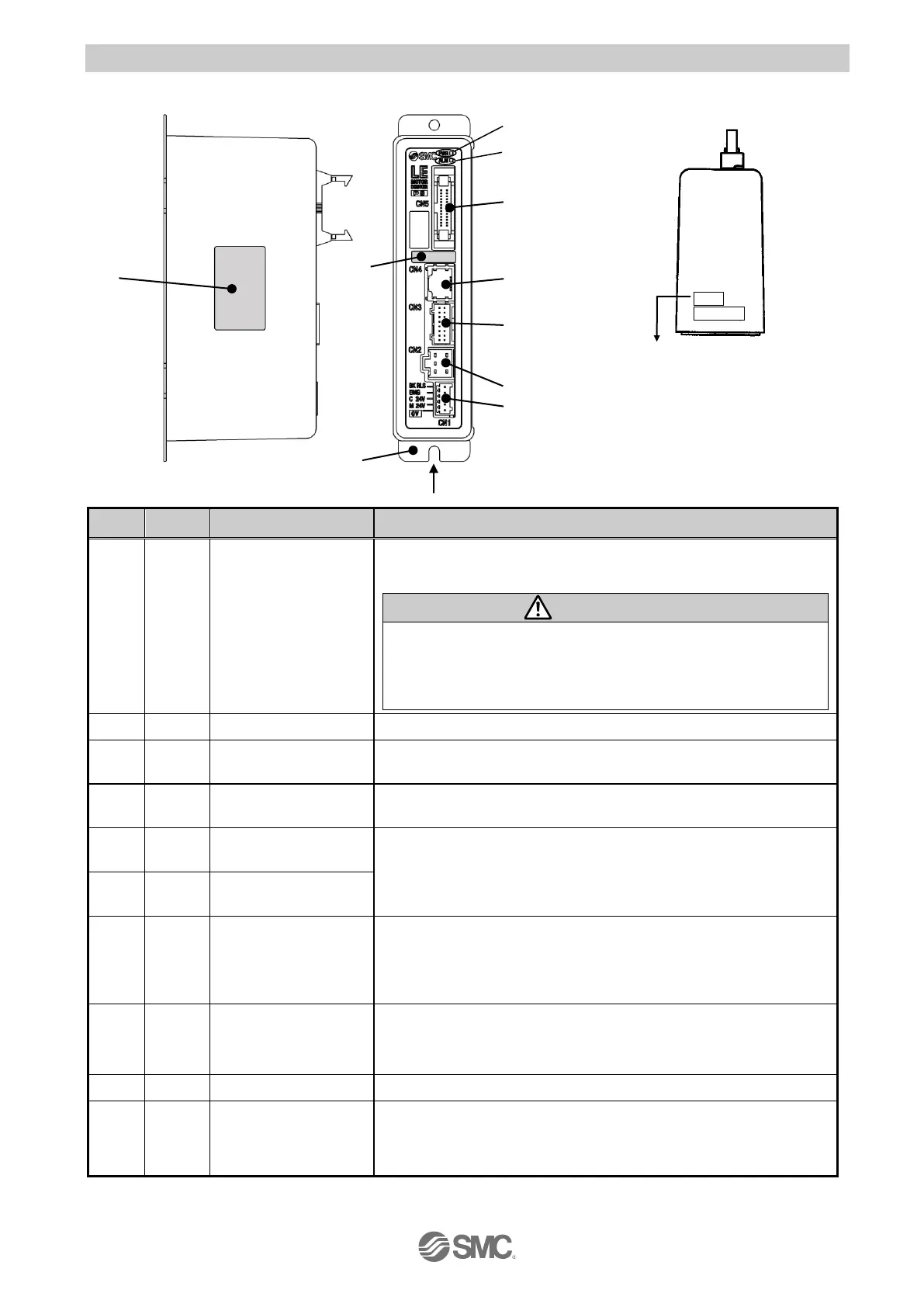
3.2 Parts description
The detailed descriptions of each part are as follows:
Power ON/No alarm: Green light
Data (step data, parameter) writing /green light flashing
Do not turn off the input power supply for the controller
while the data is being written (power supply LED (green)
flashes).
Data (step data, parameter) may not be written correctly.
Power ON/Alarm: Red light
Parallel I/O
Connector (26 pins)
Used to connect PLC, etc. with the I/O cable.
(11 inputs and COM, 13 outputs and COM)
Serial I/O
Connector (8 pins)
Used to connect the teaching box, PC, etc.
Encoder connector
(16 pins)
Used to connect the actuator cable.
Motor power
connector (6 pins)
Used to connect the controller power supply (24 VDC) with the
power supply plug.
Common power (-) ,Motor power (+) ,Control power (+) ,Stop
signal (+) ,Lock release (+)
Applicable electric
actuator model
number label
The label indicating the applicable electric actuator model.
It also indicates the type of the parallel I/O (PNP/NPN).
The label indicating the part number of the controller.
Functional ground
(When the controller is mounted, tighten screws and connect
the grounding cable)
A side (controller version)
Label of controller version
Example) controller version “SV1.00”
(1)
(2)
(3)
(4)
(5)
(6)
(7)

 Loading...


