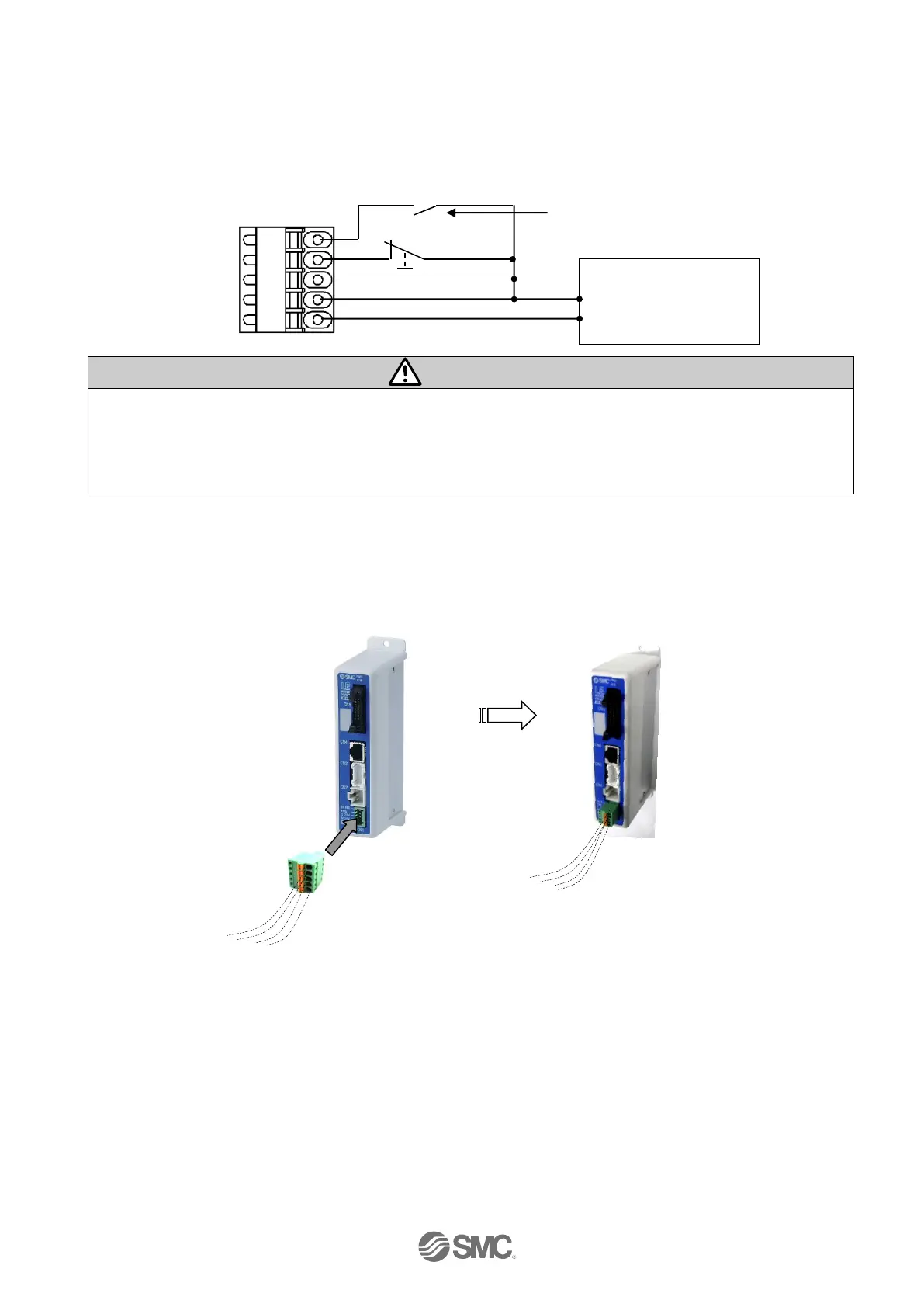
(3) Wiring of the lock release
Install an unlocking switch for adjustment or recovery during an emergency of the electric actuator with
lock. The switch (24 VDC, Contact capacity: 0.5A or more) should be obtained separately.
One terminal of the lock release switch should be connected to the 24 VDC power supply and the other
should be connected to the BK RLS terminal. When this is switched on, the lock will be released forcibly.
Power supply plug
(1) If the electric actuator is a non-lock type, it is not necessary to wire the BK RLS terminal.
(2) Do not supply power to the BK RLS (lock release) during normal operation.
The 24 VDC supply to the BK RLS (lock release) is only required for the adjustment and the recovery
in the emergency.
After the wiring of the power supply plug is completed, connect it to the CN1 connector of the controller.
Please refer to “5.3 Wiring of power supply plug” for how to wire the power supply plug.
Controller Power supply plug connected to CN1
Power supply plug
BK RLS
EMG
C 24V
M 24V
0V
(External stop
circuit)
 Loading...


