- 7 -
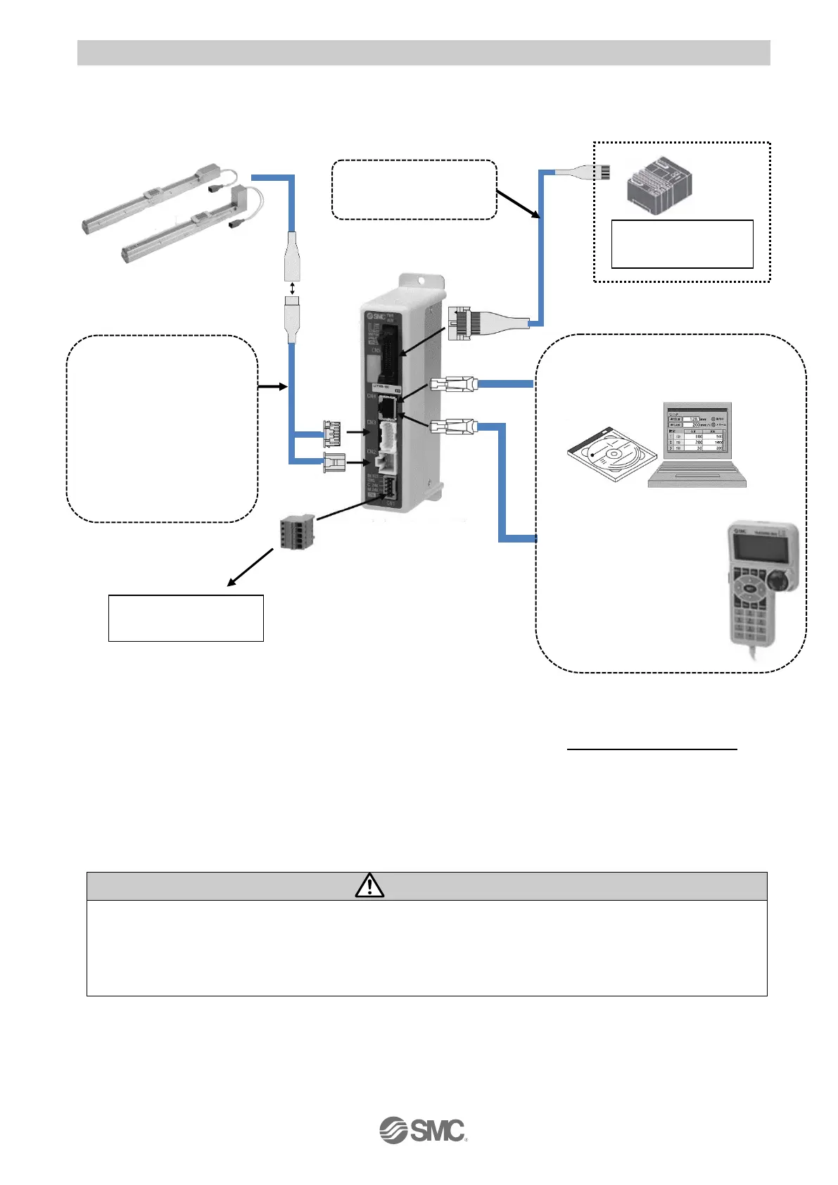
2.2 Product configuration
The product configuration of this controller is as follows.
●Electric actuator
*1)
Prepared by user
*6)
*1) *6)
*6)
*3)
●Power supply plug (accessory)
Applicable cable size
AWG20 (0.5mm
P2P
)
*1) These items are included when ordered using the part number for the electric actuator set.
*2) The controller setting software must use the latest version.
For version information and upgrade, please refer to the SMC website. http://www.smcworld.com/
*3) When conformity to UL is required, the electric actuator and controller should be used with a UL1310
Class 2 power supply.
*4) 24 VDC power supply for controller input and 24 VDC power supply for I/O signal should be separated.
*5) PC is prepared by the user.
*6) Optional.
Refer to section “4. External Connection for wiring”
Refer to “13. Precautions for wiring and cables” when handling the wiring and cables.
Do not connect the teaching box, LAN equipment, or LAN cable directly to a PC.
Otherwise, the controller, PC or equipment may be damaged.
 Loading...


