- 29 -
6.3 The parallel I/O signal is detailed
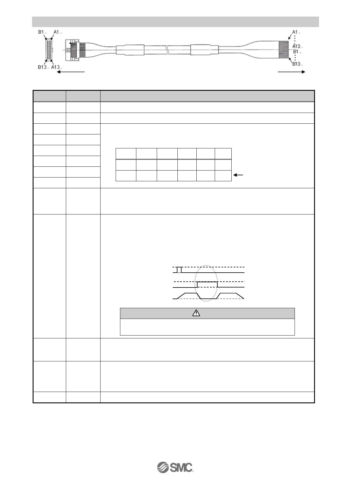
- Input terminal-
The terminal for the 24V of the 24 VDC I/O signal power.
The terminal for the 0V of the 24 VDC I/O signal power.
Bit no. to specify the step data
(Specify the number by combining On / Off of the terminals.)
Example: (Bit no. to specify the step data no.3.)
When SVRE (B11) is ON, the SETUP operation (return to origin operation) will be
performed. During the SETUP operation, BUSY (B7) will be turned ON and after
completion of the SETUP operation, SETON (B9) and INP (B10) will be turned ON.
If HOLD input is ON during operation, the speed decreases at maximum
deceleration speed of the basic parameter until the electric actuator stops. The
remaining stroke will be on hold as long as HOLD is ON and when HOLD is
turned OFF, the electric actuator restart to travel the remaining stroke.
● When DRIVE or SETUP is ON:
As long as HOLD is ON, the DRIVE input will be disabled.
The output signals are rendered invalid whilst hold is in operation.
When DRIVE is turned ON, the system scans the input IN0 to IN5 and starts the
operation of the electric actuator. Then, when this terminal is turned OFF, the number
of the active step data will be output via the terminals OUT0 to OUT5.
The terminal to reset the alarm and the operation. After RESET, the speed decreases
at maximum deceleration speed of the basic parameter until the electric actuator
stops. INP and OUT0 to OUT5 will be turned OFF (however, if the electric actuator is
stopped within the in-position range, the INP will be turned ON).
The SVON signals turns the servomotor ON/OFF.
*1)
*1) When power is applied, it may take up to 10 seconds (max. 20 sec.) from SVON input to SVRE output
depending on the electric actuator position.
Connector for CN5 of the controller
The end to be connected to a PLC, etc.

 Loading...


