EasyManuals Logo

SMC Networks LECP6 Series User Manual

SMC Networks LECP6 Series
72 pages
To Next Page IconTo Next Page
To Previous Page IconTo Previous Page
Page #22 background image
- 21 -
PC
(The PC should be obtained separately.)
󱧉 󲎠󰕹
100
500
200
1000
50
200
1
2
3
󳠠󳠚󳠡
󳠠󳠚󳠡
󳠠󳠚󳠡
󱋈󰄟󱧉
120.3
󱋈󰄟󲎠󰕹
200
mm
mm/s

󳛑󳜘󳜫󳜏
ニタ
設定
󱧉 󲎠󰕹
100
500
200
1000
50
200
1
2
3
󳠠󳠚󳠡
󳠠󳠚󳠡
󳠠󳠚󳠡
󱋈󰄟󱧉
120.3
󱋈󰄟󲎠󰕹
200
mm
mm/s

󳛑󳜘󳜫󳜏
モニタ
設定
PLC, etc.
(The PLC, etc. should be obtained separately.)
(2) Connection with a PC
Controller setting kit
Controller
Caution
(1) Do not connect to equipment other than specified (LEC-W1, LEC-W2, LEC-T1, LEC-G).
When connected to equipment which is not specified, the product will be damaged by incorrect
signal wiring.
(2) When connecting the cable, make sure that no electrically conductive materials are present in
the connector insertion port.
(3) In the LEC-W1, the 0V of the driver and PC is not insulated.
If the 0V and the PC ground are common and the PC ground makes contact with another
voltage, an excessive voltage might be applied to the driver, causing damage to the
driver.
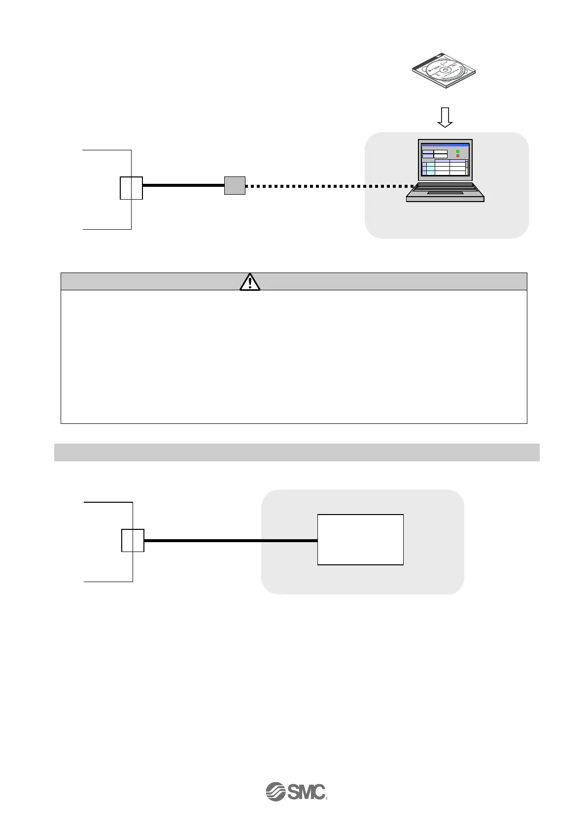
4.4 CN5: Parallel I/O connector
Controller
CN5
Please refer to “6.4 Parallel I/O Wiring Example” for how to wire the CN5 connector.
Please refer to "6.3 The parallel I/O signal is detailed" for details of each signal of parallel I/O.
CN4
Communication
cable
USB cable
(A-miniB type connector)
I/O cable

Table of Contents

Other manuals for SMC Networks LECP6 Series

Questions and Answers:

Question and Answer IconNeed help?

Do you have a question about the SMC Networks LECP6 Series and is the answer not in the manual?

SMC Networks LECP6 Series Specifications

General IconGeneral
BrandSMC Networks
ModelLECP6 Series
CategoryController
LanguageEnglish

Related product manuals