The earthling should be the dedicated grounding point. It should be a functional ground with less than
100 Ω resistance.
The cross section of the grounding wire should be greater than 2mm
2
.
The ground point should be near this controller to make the wire length shorter.
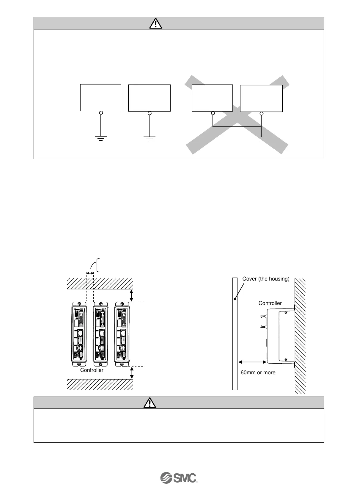
Recommended Functional grounding Not Recommended grounding
(3) Installation location
Select the size and the installation style so that the surrounding temperature of the controller is 40
o
C or
less.
Mount the controller vertically on the wall with the space allowed as shown in Fig. 1.
As shown in Fig. 2, establish the construction so that the connectors can be connected and
disconnected.
Enough space must be allowed around the controller so that the operating temperature of the controller
stays within the specification range.
Avoid mounting the controller near a vibration source, such as a large electromagnetic contactor or
circuit fuse breaker on the same panel.
Fig.1 Fig.2 Cover (the housing)
If the mounting surface of the controller is distorted or not flat, excessive force may be applied to the
housing, etc. causing malfunction.
Mount this product on a plane flat surface.
0mm or more: Body size 16 or less *Only the LEH series apply to all size
10mm or more: Body size 25 or more *Except for LEH Series
30mm or more (screw mount type)
50mm or more (DIN rail mount type)

 Loading...


