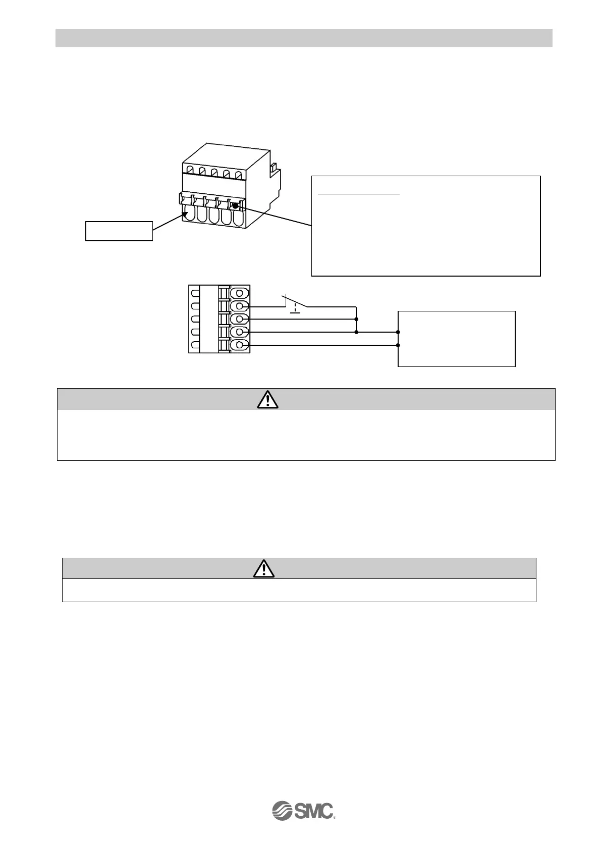
5.3 Wiring of power supply plug
Connect the power supply plug to the 24 VDC controller power supply according to instructions (1) (2)
and (3) and then, insert it into the CN1 connector of the controller.
(1) Wiring of the power supply
Connect the positive of the 24 VDC controller power supply of the controller to the C24V, M24V and
EMG terminal of the power supply connector, and connect the negative of that power supply to the 0V
terminal.
For controller input power supply (24 VDC) use a power supply with a capacity not less than the
“momentary maximum power” of the electric actuator specification. Do not use “inrush current restraining
type” power supply.
(2) Wiring of the stop switch
By connecting 24V to EMG, motor becomes operable. Without connect the 24V to EMG, motor does not
move. Stop switch must be installed by the user to stop the electric actuator in abnormal situations.
Please refer to “5.4 Stop circuits” for examples of how to wire stop switches.
The Servo is not ON unless a voltage of 24 VDC is applied to the EMG terminal.
Open/Close lever
Press these levers with the special driver, etc.
and insert electric wires into the entries.
●Special driver (recommended)
Part no: SZS0.4 x 2.0
(Manufactured by Phoenix Contact)
(External stop circuit)

 Loading...


