If the stop is input from the EMG or RESET terminal or the stop-switch on the connected
Teaching Box during pushing operation, the electric actuator stop. (“Busy” signal turns OFF)
If the electric actuator stops within the range of “Position”± “In posn” as defined in the step
data, the output signal “INP” will turn ON.
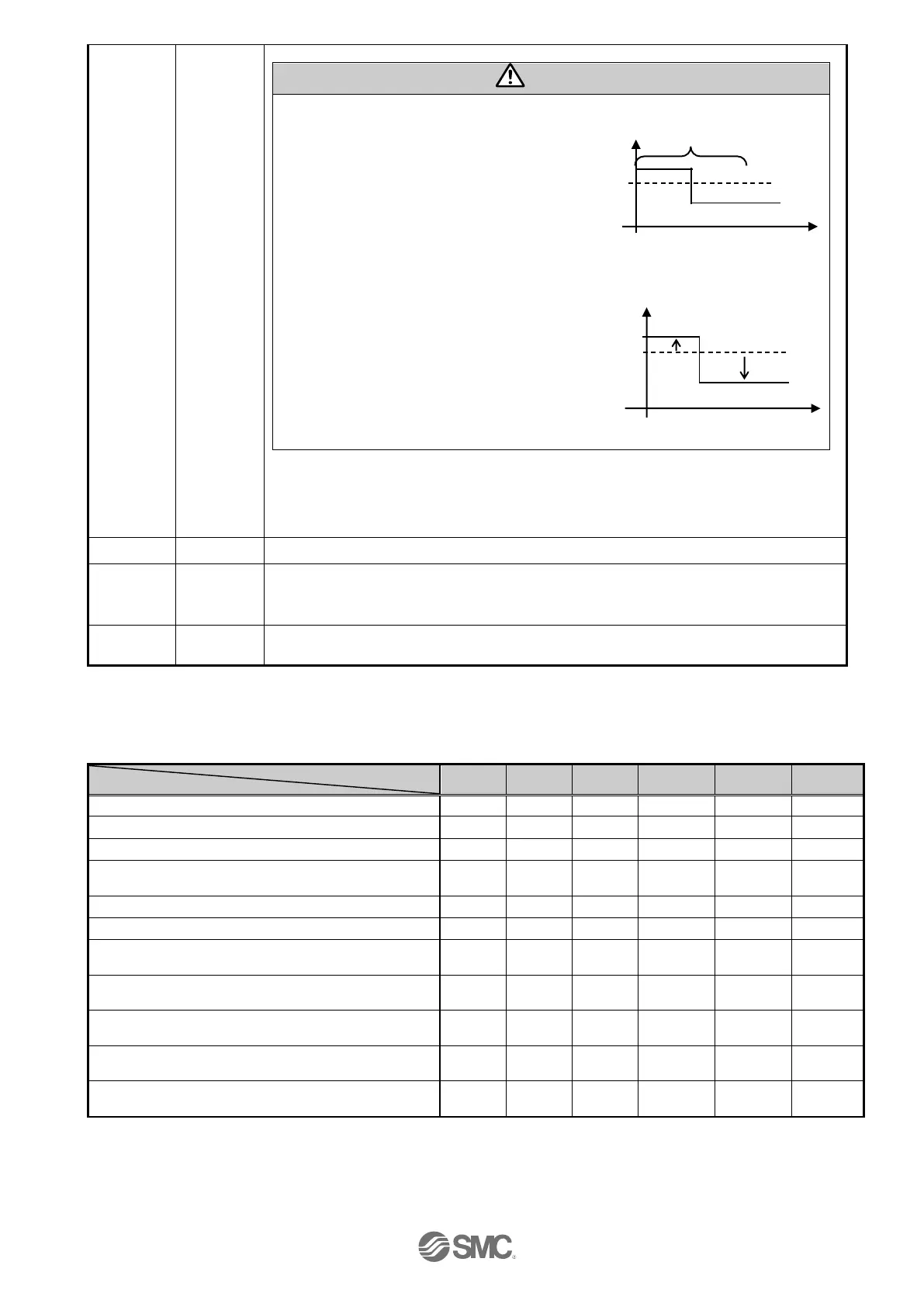
(1) After pushing operation is finished, even if controller changes to energy saving
mode, “INP” signal status maintains to ON.
(Example) Step data “force” is 100%
Step data “Trigger LV” is 80%,
The energy saving setting of the
electric actuator is 40%
*1)
(2) If controller version is below SV1.00.
During pushing operation in energy saving mode, if the energy saving setting is less
than the Trigger LV value, the INP output signal will turn OFF.
When movement starts again from the pushing stopped state, it will do pushing
operation with energy saving pushing force.
(Example) Step data “force” is 100%
Step data “Trigger LV” is 80%
The energy saving setting of the
electric actuator is 40%.
*1)
*1) The electric actuator model determines the energy settings.
Please refer to the specifications of the electric actuator for more details.
When the servomotor is OFF, SVRE is OFF. When the servomotor is ON, SVRE is ON.
(*1)
During activation of Teaching Box stop switch, this terminal is OFF. During the normal
operation, this is ON. This is synchronized to the input terminal for the EMG signal on the
controller connector CN1.
When there are no alarms, this terminal is ON.
When there are alarms, this is OFF.
*1) When power is applied, it may take up to 10 seconds (max. 20 sec.) from SVON input to SVRE output
depending on the electric actuator position.
*2) The “*ALARM” and “*ESTOP” are the negative-true logic output.
The table below shows the changes in the output signal with respect to controllers state.
Controller powered down [SVOFF] with no motion
Controller powered down [SVON] with no motion
During returning to origin, [SETUP].
The electric actuator is at the origin. On completion of
[SETUP]
During movement by positioning/ pushing operation.
The electric actuator is paused by [HOLD]
On completion of the positioning operation.
(within “In position”)
Stopped due to pushing a work-load in pushing
operation. (holding)
Stopped due to no detection of work-load during a
pushing operation.
On completion of return to origin and then with [SVON]
turned off.
EMG signal stop from the CN1 connector after the
electric actuator is at the origin.
*1) The output turns on when the electric actuator is within the range defined in the basic parameter setup.
*2) The output is updated on the transition of (ON→OFF) of the DRIVE input signal.
*3) Retains the previous state.
*4) The output turns on when the electric actuator is “In position” of the step data.
time
time
80
100
40
forc
e
B6

 Loading...


