3
Series ITV1000/2000/3000
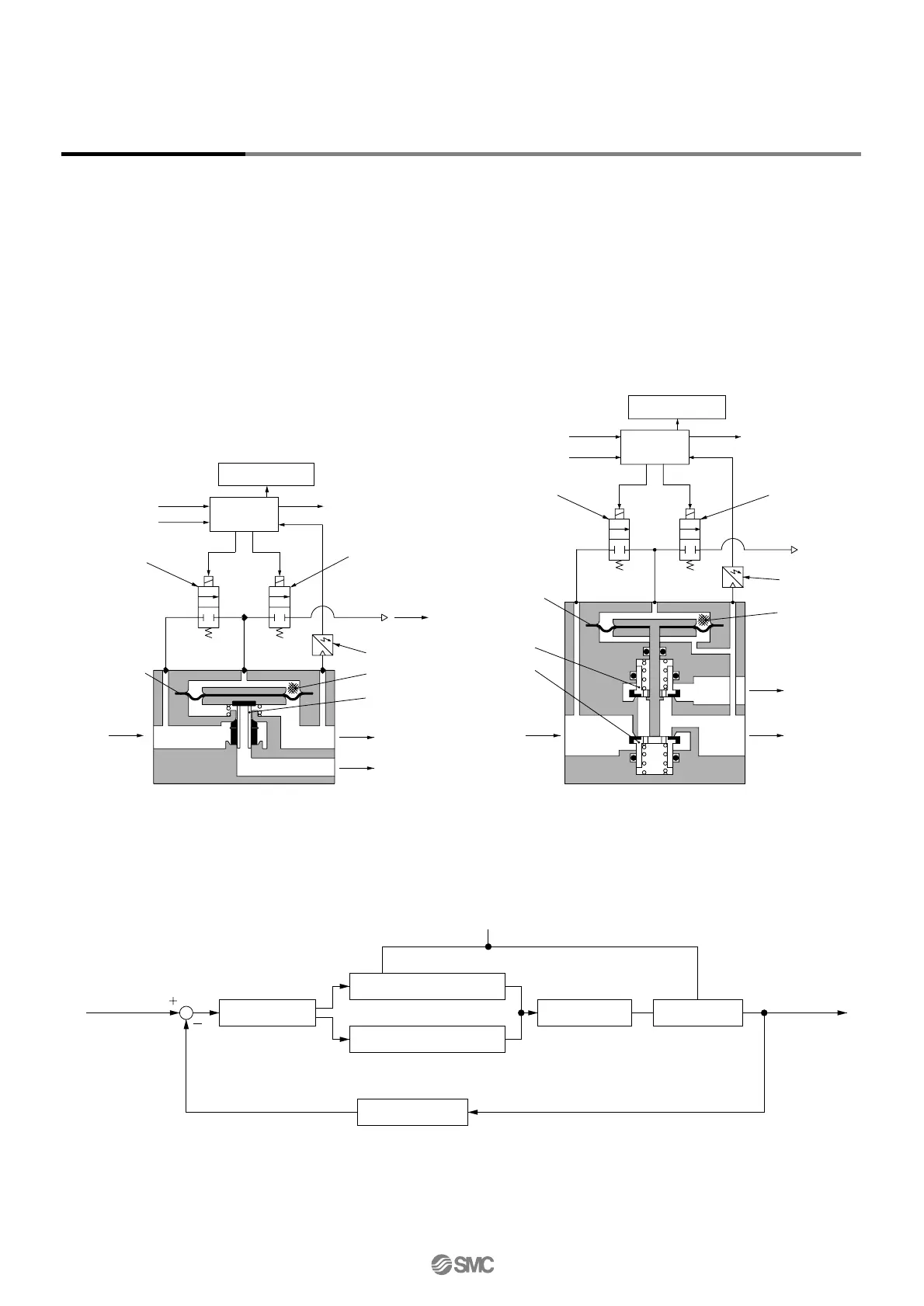
Working Principles
Supply pressure
q Air supply solenoid valve
w Exhaust solenoid valve
r Diaphragm
i Control circuit Pilot valve
u Pressure sensor
Input signal Output pressure
Block diagram
When the input signal rises, the air supply solenoid valve q turns ON, and the exhaust
solenoid valve w turns OFF. Therefore, supply pressure passes through the air supply
solenoid valve q and is applied to the pilot chamber e. The pressure in the pilot
chamber e increases and operates on the upper surface of the diaphragm r.
As a result, the air supply valve t linked to the diaphragm r opens, and a portion of
the supply pressure becomes output pressure.
This output pressure feeds back to the control circuit i via the pressure sensor u.
Here, a correct operation functions until the output pressure is proportional to the input
signal, making it possible to always obtain output pressure proportional to the input
signal.
Working Principle Diagram
ITV2000, 3000
Pressure display
Power supply
Input signal
q Air supply
solenoid
valve
r Diaphragm
y Exhaust
valve
t Supply
valve
w Exhaust
solenoid
valve
Output signal
u Pressure
sensor
e Pilot
chamber
i Control
circuit
SUP OUT
EXH
EXH
ITV1000
SUP
EXH
OUT
EXH
t Supply valve
w Exhaust
solenoid
valve
u Pressure sensor
q Air supply
solenoid
valve
Input signal
Power supply
Output signal
r Diaphragm
e Pilot chamber
Pressure display
i Control
circuit

 Loading...