Installation
22
Burner and nozzle characteristics table
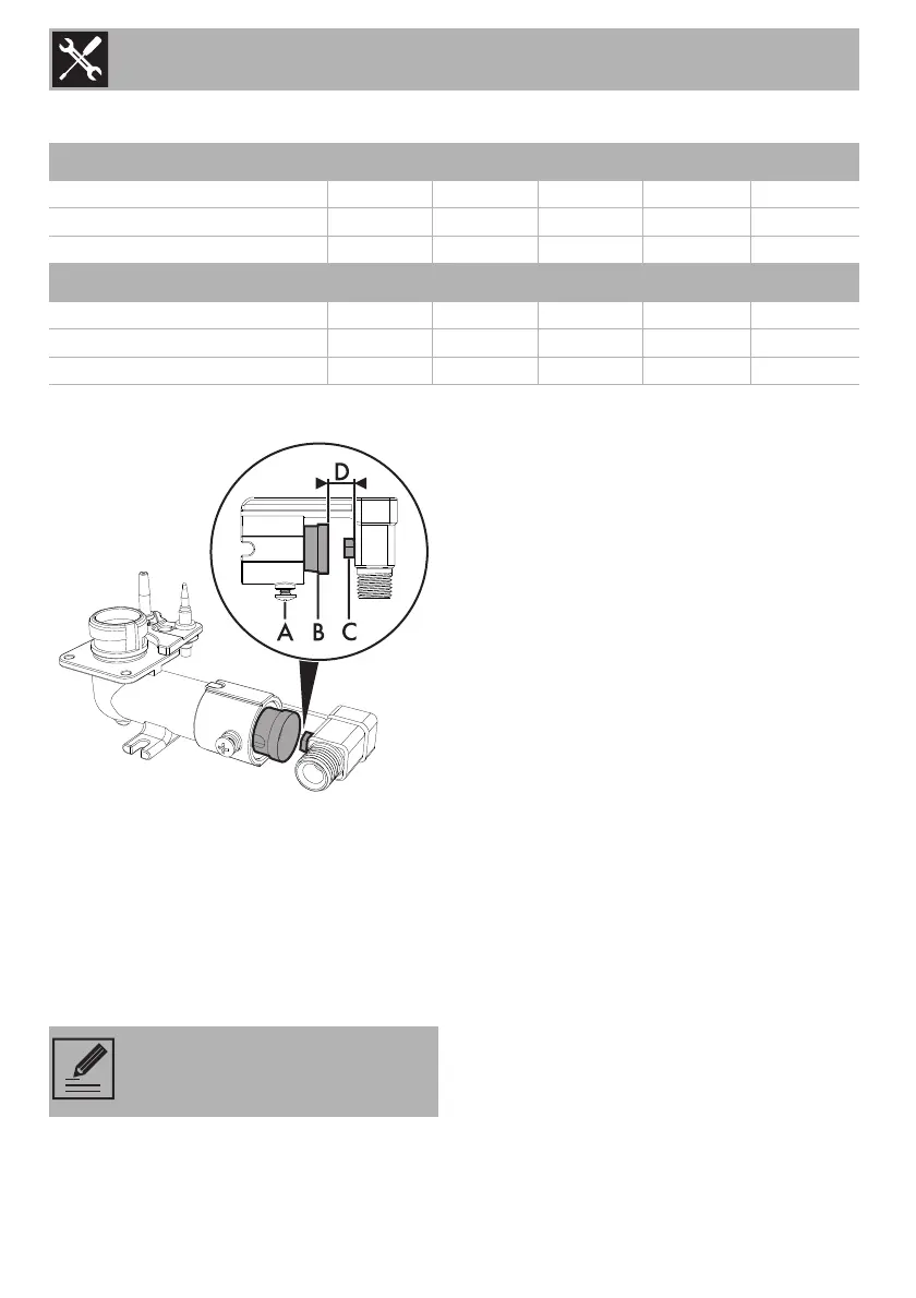
Replacing nozzles
1. Unscrew screw A and push air regulator
B as far as it will go.
2. Use a spanner to remove the nozzles C
and install the new ones for the required
gas supply, following the indications
given in the relevant table (see “Burner
and nozzle characteristics table”).
3. Adjust the air flow by moving the air
regulator B to obtain the distance D
given in the relevant table (see “Burner
and nozzle characteristics table”).
4. After adjusting each burner, reassemble
the appliance correctly.
Adjusting the minimum setting for natural
gas
Light the burner and turn it to the minimum
position. Extract the gas tap knob and turn
the adjustment screw next to the tap rod
(depending on the model) until the correct
minimum flame is achieved.
Refit the knob and verify that the burner
flame is stable. Turn the knob rapidly from
the maximum to the minimum setting: the
1 ULPG 2.75 kPa AUX SR RR R1 R2
Nominal gas consumption (MJ/h)
4.1 6.0 9.4 14.5 10.8
Injector (1/100 mm)
54 67 82 100 85
Primary air (mm)
422103
2 NG 1.0 kPA AUX SR RR R1 R2
Nominal gas consumption (MJ/h)
4.7 6.1 9.4 14.5 10.8
Injector (1/100 mm)
98 110 135 170 145
Primary air (mm)
4326 5
The nozzle tightening torque must
be no more than 3 Nm.
 Loading...