Issue/Rev. 0.7 (11/17) MN01045 • Page 3
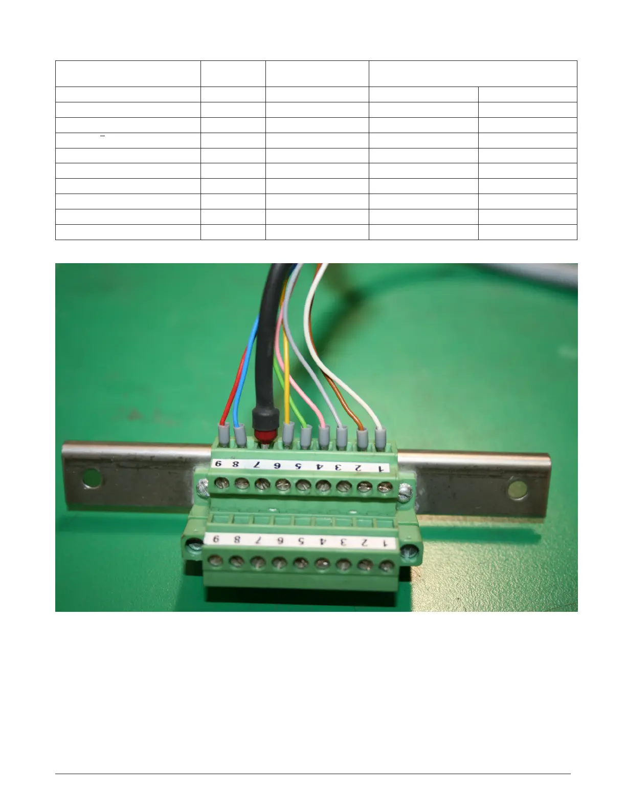
Figure 1 – Terminal Block Wires
Note: Picture in color, black and white, follow wire diagram table.
Wiring Diagram
Function Color
Standard Version Pin
Connections
Rotation of Transmitter Shaft Reference
Dimensions Drawing Below
Electronics Ground white
[ 1 ]
Input Power (12-24 Vdc) brown
[ 2 ]
Counter-Clockwise Clockwise
Channel "B" Output grey
[ 3 ]
Leading Lagging
Channel "B" Output pink
[ 4 ]
Channel "A" Output green
[ 5 ]
Lagging Leading
Channel "Ā" Output yellow
[ 6 ]
Shield black
[ 7 ]
Verication Pulse Output blue
[ 8 ]
Inverted Verication Pulse red
[ 9 ]
(Not used)
[10]