General
The Smith Meter
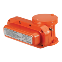
®
Model UPT (Universal Pulse) Transmit-
ter is a photo-electric, dual channel, high resolution, pulse
generator that is directly connected to the output shaft of a
positive displacement meter.
The UPT Transmitter is installed at the lowest level in the
meter accessory stack. It is designed to be mounted directly
on the meter dome adaptor and replaces the manual cali-
brator. If other mechanical stack accessories are required,
a calibrator adaptor kit is used for mounting the manual
calibrator above the UPT Transmitter.
Reference Publications
Specication Bulletin SS01105
Parts List PO01056 (P0907.05)
Receipt of Equipment
When the equipment is received, the outside packing case
should be checked immediately for any shipping damage.
If the packing case has been damaged, the local carrier
should be notied at once regarding his liability. Carefully
remove the unit from its packing case and inspect for
damaged or missing parts.
If damage has occurred during shipment or parts are
missing, a written report should be submitted to the Inside
Sales Department, Measurement Solutions, PO Box 10428,
Erie, Pennsylvania 16514.
Prior to installation, the unit should be stored in its original
packing case and protected from adverse weather condi-
tions and abuse.
Mechanical Installation
When ordered with a Smith Meter
®
positive displacement
(PD) meter, the Model UPT Transmitter will normally be
factory installed directly on the meter. The following steps
are required for eld mounting the UPT Transmitter to a
Smith Meter PD meter:
1. Remove all accessories (counters, mechanical temperature
compensators, transmitters, etc.) from the meter.
2. Remove the existing calibrator, located inside the meter
dome adaptor.
a. Remove the cap protecting the external calibrator
adjusting stem by removing the two mounting screws.
b. Indicate the calibrator setting with a line that intersects the
calibrator dial and its adjacent part.
c. Remove the calibrator adjusting assembly by removing
the two mounting screws and carefully withdraw the stem
assembly from the housing without changing the adjusting
screw.
d. Remove the calibrator from the meter dome adaptor by
removing the two small hold-down screws and carefully
rotating the calibrator body clockwise.
e. Attach the blind plate (provided in the adaptation
kit) over the calibrator stem assembly hole.
Universal Pulse Transmitter (UPT)
Installation/Service
Bulletin MN01045 Issue/Rev. 0.7 (11/17)
MANUAL