TRAK MODEL 9100 MODULAR FREQUENCY/TIME SYSTEM
2-6
TM4400013 Rev. D
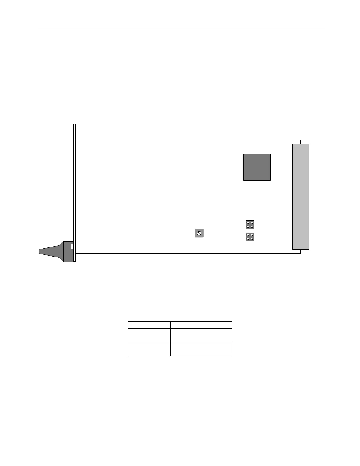
2-8.2 Model 9107 Frequency Distribution Module (FDM) Module Jumper Settings
The FDM provides four outputs of the selected reference signal. Each FDM can be set with internal jumpers on
E1 and E2 to output 10 MHz or IRIG B. Refer to Figure 2-3 for jumper location and Table 2-8 for FDM selector
output jumper settings.
The FDM also has a potentiometer (R2) for adjusting the output signal level of the four outputs. The
potentiometer is factory set to 2.8 VPP into 50 ohms.
Figure 2-3, FDM Output Jumper Locations
Table 2-8, FDM Output Signal Jumper Positions
Output Jumper Positions
10 MHz E1, Jumper 1 and 2
E2, Jumper 1 and 2
IRIG-B E1, Jumper 3 and 4
E2, Jumper 3 and 4
E1
12
34
E2
1
2
3
4
R2
IRIG-B, A
IRIG-B, B
10 MHz, A
10 MHz, B
Output Level
Trim Adj.
FDM