TRAK MODEL 9100 MODULAR FREQUENCY/TIME SYSTEM
2-7
TM4400013 Rev. D
2-8.3 Model 9111 TEL Module Switch and Jumper Settings
The Model 9111 is factory configured for either T1 or E1 telecommunications outputs and cannot be field
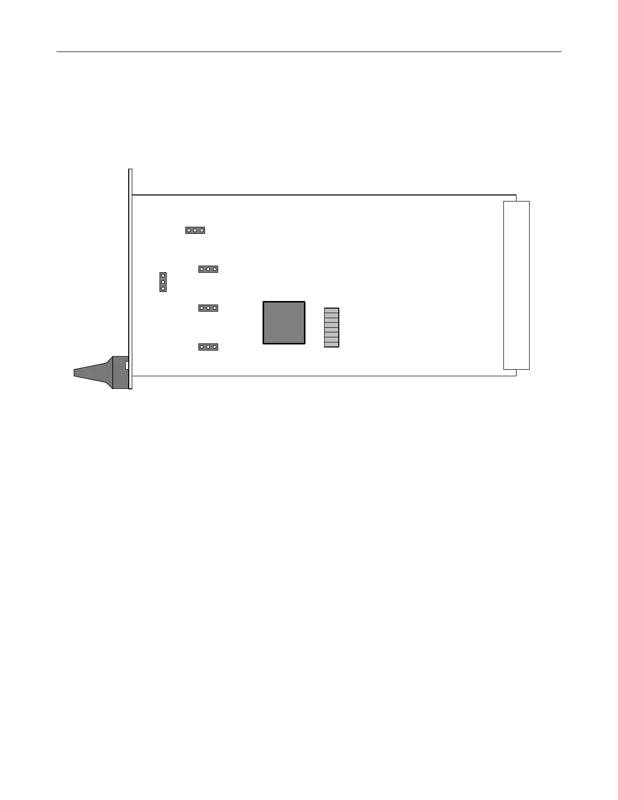
changed. This includes both clock and framed signals. Refer to Figure 2-4 for selector switch location and
Tables 2-9, 2-10, and 2-11 for TEL selector switch settings. Refer to Tables 2-12 and 2-13 for RS-422 Clock and
Framed outputs.
Figure 2-4, TEL Selector Switch and Jumper Location
Model 9111-1 TEL Module Switch and Jumper Settings for T1
Output Ground Isolation (Factory configured)
R33 – R36 Zero Ohm resistors not installed (Isolated)
Clock Select (Factory configured)
J3, jumper pins 1 and 2 (1.555 MPPS)
Output Transformer Impedance Select (Factory configured)
J5 – J8, jumper 1 and 2 (120Ω)
S1
1
8
Framing
Select
J3
123
123
123
123
1
2
3
E1 T1
T1 - E1
Clock
Sel.
J5 - J8
Output Z
Sel.
J7
J6
J5
J8
TEL