TRAK MODEL 9100 MODULAR FREQUENCY/TIME SYSTEM
2-8
TM4400013 Rev. D
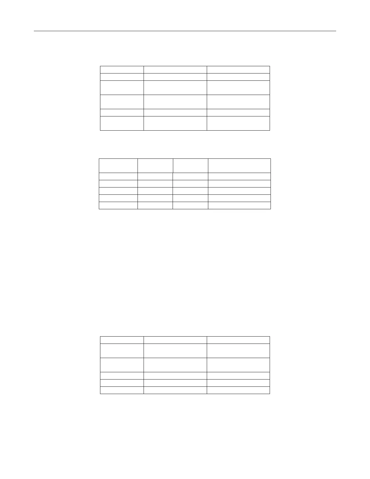
Table 2-9, TEL Framing Format Switch Positions for T1
S1 Settings On Off
S1-4 B8ZS Disabled B8ZS Enabled
S1-5 Transparent Zero
Suppression
Bit 7 Stuffing Zero
Suppression
S1-6 Yellow Alarm
Transmit Disabled
Yellow Alarm
Transmit Enabled
S1-7 193S Select 193E Select
S1-8 Internal 193S Bit
Selection
External 193S Bit
Selection
Table 2-10, TEL Line Length Compensation Switch Positions for T1
S1-1
Settings
S1-2
Settings
S1-3
Settings
Line Length
On Off Off 1 – 133 Feet
Off On On 133 – 266 Feet
Off On Off 266 - 399 Feet
Off Off Off 399 – 533 Feet
Off Off Off 533 – 655 Feet
Model 9111 TEL Module Switch and Jumper Settings for E1
Output Ground Isolation (Factory configured)
R33 – R36 Zero Ohm resistors not installed (Isolated), for balanced 120Ω output
R33 – R36 Zero Ohm resistors installed (non-Isolated), for unbalanced 75Ω output
Clock Select (Factory configured)
J3, jumper pins 2 and 3 (2.048 MPPS)
Output Transformer Impedance Select (Factory configured)
J5 – J8, jumper 1 and 2 (120Ω)
J5 – J8, jumper 2 and 3 (75Ω)
Table 2-11, TEL Framing Format Switch Positions for E1
S1 Settings On Off
S1-4 Transmit CAS
M frame enabled
Transmit CAS
M frame disabled
S1-5 Transmit CRC4
M frame disabled
Transmit CRC4
M frame enabled
S1-6 Data AMI encoded Data HDB3 encoded
S1-7 TDMA normal TDMA alarm enable
S1-8 TRA normal TRA alarm enable
 Loading...