2
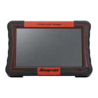
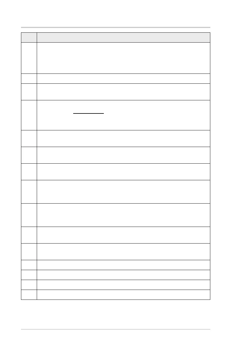
Feature Identification
Item Description
1
Battery Status Indicator LED
• Green - battery is fully charged
• Red - battery is charging
• Amber - indicates there is a battery issue (correct before operating)
2 DC Power Supply Jack - AC/DC power supply connection
3
Mini USB Jack - USB cable connection used to transfer saved data files
to a personal computer
4
Micro secure digital (uSD) Card - Contains operating system
programming. IMPORTANT
The uSD card must be installed to
operate the diagnostic tool. Do not remove the uSD card while the
diagnostic tool is turned on.
5
Data Cable Connector - Data cable connection used to connect the
diagnostic tool to a vehicle data link connector
6
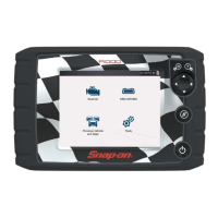
Touch Screen - User interface to make onscreen menu and control
selections
7
N/X or Cancel Button - Push type button used to exit a menu or
program, return to the previous screen, or provide a “no” answer
8
Y/
a or Accept Button - Push type button used to accept or confirm a
selection from a menu, advance to the next screen, or provide a “yes”
answer
9
Directional Button - Thumb pad rocker type buttons used to move the
highlight/focus on the screen up, down, left, and right, as indicated by the
arrows.
10
Shortcut Button - Push type programmable button used to perform a
variety of routine tasks.
11
Power (On/Off) Button - Push type button used to turn the diagnostic
tool on and off. For emergency shutdown, press and hold for 5 seconds.
12 Battery Pack
13 Battery Pack Cover
14 Battery Pack Cover Screws (2)
15 Built-in Stand (shown closed)