3
Basic Navigation
z Battery Installation / Power Connection
1. Loosen the battery pack cover screws (located on back) and
remove the battery pack cover.
2. Align the locating tabs and install the battery pack.
3. Install the battery cover and tighten the screws.
DO NOT overtighten the battery cover screws.
The battery pack is supplied charged, however if needed
connect the AC/DC power supply to an appropriate power
source and into the “10-30V” DC power supply jack on top of the
diagnostic tool.
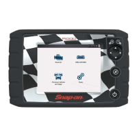
z Turning the Diagnostic Tool On
Press and release the power button on the front of the
diagnostic tool to turn the diagnostic tool on.
i The diagnostic tool automatically turns on when connected
to an external power source, such as the AC/DC power
supply or a vehicle data link connector (DLC).
Basic Navigation
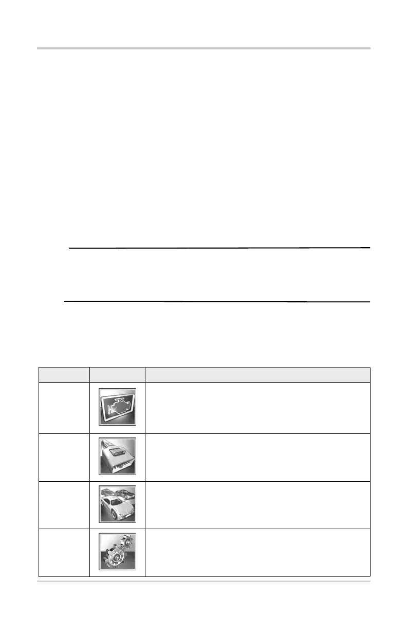
Home Screen Icons
Name Icon Description
Scanner
Used to communicate with the electronic control
systems of a vehicle. Retrieve diagnostic trouble
codes (DTCs), view PID data and perform diagnostic
tests.
OBD-II/
EOBD
Access generic OBD-II/EOBD data and tests without
identifying the vehicle being tested.
Previous
Vehicles
& Data
Quickly reconfigure the diagnostic tool to a recently
tested vehicle and access saved data files.
Tools
Adjust diagnostic tool settings to your personal
preferences and perform other special functions.