EasyManua.ls Logo

Snapper 6-3317 User Manual

Snapper 6-3317
8 pages
To Next Page IconTo Next Page
Page #1 background imageLoading...
Page #1 background image
1
#6-3317 SINGLE BAG GRASS CATCHER for SNAPPER
REAR ENGINE RIDERS with 28/33” DECKS & LAWN TRACTORS with 33” DECKS
This grass catcher kit fits Lawn Tractors with 33” Decks and Rear Engine Riders with 28” & 33” Decks. On
Series “A” & Later Lawn Tractors, Adapter Kit #6-1334 must be installed before this grass catcher can be
installed. On Series “0-2” Lawn Tractors, Adapter Kit #6-1068 must be installed before this grass catcher can
be installed. Install adapter kit as described by instructions provided with kit.
WARNING
DO NOT attempt any maintenance, adjustments,
service, or repairs with engine running. STOP
engine. STOP blade. Set park brake. Remove key.
Remove spark plug wire and secure away from
spark plug. Engine and components are HOT. Avoid
burns, allow sufficient time to cool.
STEP 1: AIR LIFT INSTALLATION.
An optional Air Lift Kit 6-1777 has been included with
this grass catcher and may be installed to enhance
bagging performance in certain conditions. The air lifts
can be installed by reaching through the discharge
opening or by removing the blade. Attach one air lift to
each end of the blade using the hardware and
instructions provided in the kit. Be certain to install lifts
on both ends of blade. Torque nuts and bolts on air lifts
to 20 to 30 ft. lbs. Torque blade retaining hardware to 45
to 55 ft. lbs. See Figure 1.
NOTE: Not all original equipment or accessory blades
will accept the Air Lift Kit. Contact an authorized dealer if
you have questions.
FIGURE 1
INSTRUCTION NO. 7-5437 (I.R. 1/29/03)
STEP 2: MUFFLER SHIELD
(USED ON REAR ENGINE RIDERS ONLY)
Remove both screws from right side of bumper. Remove
bolt from right side of main case. Position the muffler
shield so that the holes line up with the holes on the
bumper. Position the bumper reinforcement with top hole
of bumper. Reinstall screws and tighten securely. Install
bolt into bumper reinforcement and tighten securely into
side of main case. See Figure 2.
FIGURE 2
STEP 3: HANDLE TO TUBE MOUNTING
Position the tube handle base inside the grass tube.
Place the tube handle on the outside,
align the holes
then secure base and handle with two 1/4-20 X 3/4”
carriage bolts (heads on inside of tube) 1/4” lock
washers and 1/4-20 hex nuts on the outside and tighten
securely. See Figure 3.
WARNING
To prevent fires, keep muffler area clear of debris.
WARNING
The cutting blades and the edges of the cutting deck
are extremely sharp and can cause severe injury.
Always wear heavy leather gloves when working
around cutting blades and the cutting deck.
AIR LIFT
LOCK
WASHER
HEX
NUT
SCREW
BLADE
#6-1777 AIR LIFT KIT
28” & 33” DECKS
BUMPER
MUFFLER SHIELD
BUMPER
REINFORCEMENT
INSTALL BUMPER
REINFORCEMENT
BOLT INTO SIDE OF
MAIN CASE
Question and Answer IconNeed help?

Do you have a question about the Snapper 6-3317 and is the answer not in the manual?

Snapper 6-3317 Specifications

General IconGeneral
BrandSnapper
Model6-3317
CategoryLawn Mower Accessories
LanguageEnglish

Summary

Grass Catcher Installation Steps

General Safety Warning

Do not attempt maintenance with engine running; ensure engine is off, blade stopped, and key removed.

Step 1: Air Lift Installation

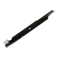
Install optional Air Lift Kit 6-1777 to blade ends using provided hardware for better bagging.

Step 2: Muffler Shield Installation (Rear Engine Riders)

Attach muffler shield to bumper and reinforcement for rear engine riders.

Step 3: Handle to Tube Mounting

Secure the grass tube handle to the grass tube using carriage bolts, washers, and nuts.

Step 4: Tube Latch to Adapter Mounting

Attach the tube latch to the chute adapter using a carriage bolt, washer, and hex nut.

Step 5: Adapter to Deck Mounting

Position and secure the adapter to the mower deck opening, ensuring proper alignment.

Step 6: Adapter Kit Installation (Tractors)

Install Adapter Kit #6-1334 as per its specific instructions for tractor models.

Step 7: Dust Skirt to Frame Installation

Attach the dust skirt to the grass catcher frame by inserting legs through holes and securing.

Step 8: Latch & Container Top Mounting

Mount the grass catcher latch and secure the container top to the frame using hardware.

Step 9: Bag Rod Assembly

Assemble the bag rod and connector, then slide the grass bag/rod into the frame.

Step 11: Weight Plate Installation (Rear Engine Rider)

Install six weights to the front frame using specified hardware for rear engine riders.

Step 12: Drill Mounting Holes (Series M Riders)

Drill two 13/32" holes on the front frame for weight plate mounting on Series M Riders.

Grass Catcher Parts Identification

Illustration of Main Components

Diagram showing the primary parts of the single bag grass catcher kit.

Illustration of Air Lift Kit and Tube Assembly

Diagram illustrating the Air Lift kit and the grass tube and adapter assembly.

Detailed Parts List

Comprehensive list of all parts, part numbers, and descriptions for the grass catcher kit.

Grass Catcher Operation and Safety

Operating Tips for Effective Bagging

Guidance on using engine speed, mower height, and mowing direction for optimal performance.

Important Safety and Maintenance Notes

Recommendations on handling dust, fertilizing, and experimenting with settings.

Related product manuals